Economic and efficient opening direct current type ice wind tunnel
An ice wind tunnel and efficient technology, applied in the testing of machines/structural components, measuring devices, instruments, etc., can solve the problems of long test period and high cost, and achieve the effect of low test cost, low manufacturing cost and simple process
- Summary
- Abstract
- Description
- Claims
- Application Information
AI Technical Summary
Problems solved by technology
Method used
Image


Examples
Embodiment Construction
[0019] In order to further understand the invention content, characteristics and effects of the present invention, the following examples are given, and detailed descriptions are as follows in conjunction with the accompanying drawings:
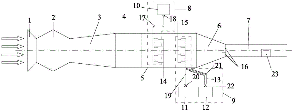
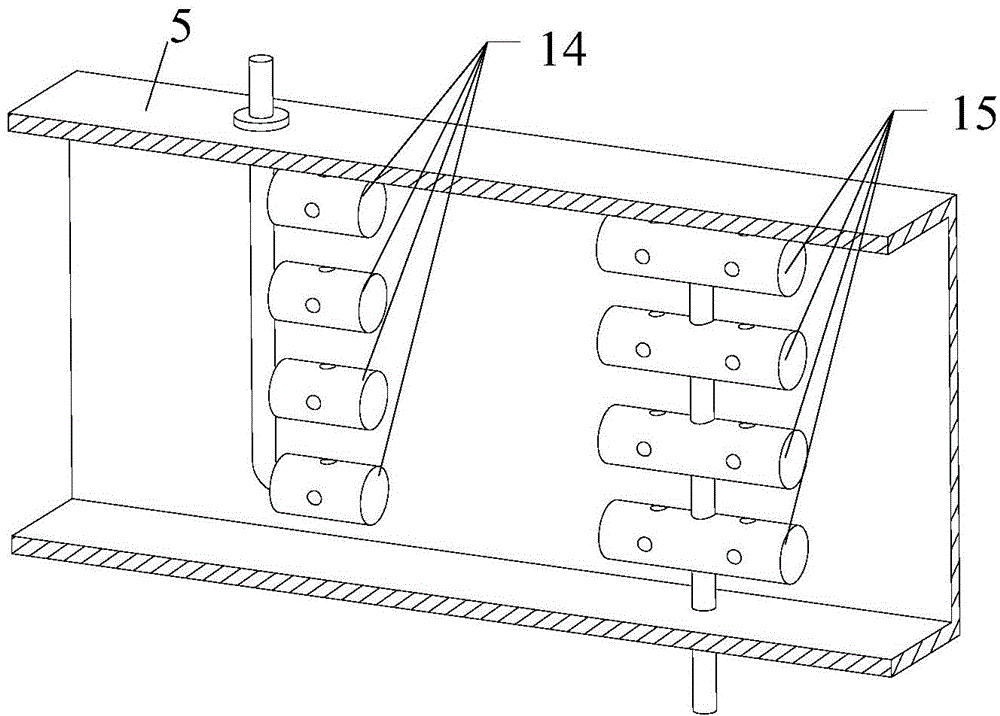
[0020] see Figure 1 ~ Figure 4 , a cost-effective open-flow direct-flow ice wind tunnel, including an air inlet 1, a power section 2, a diffusion section 3, a stabilization section 4, an ice and snow particle generation section 5, and a test section 7 connected in sequence.
[0021] The ice and snow particle generation section 5 is provided with a liquid nitrogen nozzle 14 and a pneumatic nozzle 15, the liquid nitrogen nozzle 14 is connected with the liquid nitrogen source 10 through a liquid nitrogen pipeline 17 to form a liquid nitrogen refrigeration system 8, and the pneumatic nozzle 15 passes The mixing pipeline is connected with a pressure gas source 11 and a pressure water source 12 to form a water particle generation system 9 . A fan...
PUM
 Abstract
Description
Claims
Application Information
 - Generate Ideas
- Intellectual Property
- Life Sciences
- Materials
- Tech Scout
- Unparalleled Data Quality
- Higher Quality Content
- 60% Fewer Hallucinations
Browse by: Latest US Patents, China's latest patents, Technical Efficacy Thesaurus, Application Domain, Technology Topic, Popular Technical Reports.
© 2025 PatSnap. All rights reserved.Legal|Privacy policy|Modern Slavery Act Transparency Statement|Sitemap|About US| Contact US: help@patsnap.com