Impedance detection device and method

A technology of impedance detection and impedance value, which is applied in the direction of measuring devices, measuring resistance/reactance/impedance, measuring electrical variables, etc., can solve the problems of suppressing distortion, difficulty in adaptive adjustment by designers, deafening and other problems, and achieve the effect of avoiding abnormal sound

Active Publication Date: 2015-05-20
REALTEK SEMICON CORP
View PDF7 Cites 8 Cited by
  • Summary
  • Abstract
  • Description
  • Claims
  • Application Information

AI Technical Summary

Problems solved by technology

However, sound output devices of different specifications can produce different output effects for the same sound signal, that is, the same sound signal may be moderately loud through the speaker output, but deafening through the earphone output; Pleasant to listen to on headphone output, but suppressed distortion on another type of headphone output
The above problems are mainly because the expected output impedance of the audio codec (Audio Codec) that outputs the sound signal (or the input impedance of the sound output device) does not match the actual situation, thus outputting a sound signal with too large or too small amplitude
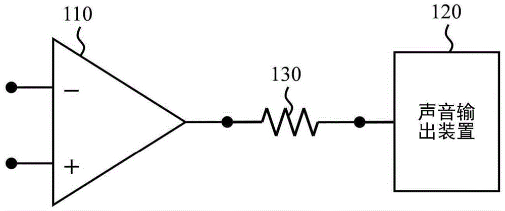
In order to adapt to a sound output device with a large input impedance (such as an active speaker, etc., the audio codec will face a large output impedance at this time) to provide a louder signal and to adapt to a sound output with a small input impedance Devices (such as passive speakers or headphones, etc., at this time, the audio codec will face a small output impedance) to provide a signal with a low volume. The current technology is in the output buffer (Output Buffer) of the audio codec A resistor 130 is connected in series between 110 and the external sound output device 120 (such as figure 1 shown) to adjust the signal energy output to the sound output device 120 through the voltage division effect of the resistor 130, however, this solution includes at least the following disadvantages: First, if the sound output device 120 has a capacitive or inductive effect, Even if the output buffer 110 does not adjust the amplitude of the output signal with the frequency, different impedance effects will be presented based on the capacitance or inductance effect as the frequency changes, and the sound effect of the sound output device 120 will still have different volumes at high and low frequencies. What's more, Because sound output devices with different specifications may have different capacitance or inductance effects, it is difficult for designers to make comprehensive adaptive adjustments; secondly, the path from the audio codec to the audio output hole on the circuit board is usually very long, which is easily affected. Noise interference, when the resistor 130 is not set, the output buffer 110 can still reduce the noise coupling effect through a very low output impedance, but in the case of setting the resistor 130, the anti-noise capability of the output buffer 110 will be reduced instead; Third, usually the resistor 130 is a passive component with a fixed resistance on the circuit board, but there are many specifications of the sound output device 120, it is difficult for the designer to use the resistor 130 with a fixed resistance to match all the sound output devices, so there will be The problem of neglecting the other

Method used


Image

  • Impedance detection device and method
  • Impedance detection device and method
  • Impedance detection device and method

Examples


Embodiment Construction

[0041] The technical terms in the following description refer to the customary terms in this technical field. If some terms are explained or defined in this manual, the explanations of these terms shall be based on the descriptions or definitions in this manual.

[0042] The disclosure of the present invention includes an impedance detection device and method for detecting the impedance of a load. The device and method can be applied to an integrated circuit (such as an audio codec (Audio Codec)) or a system device (such as a computer, mobile phone, music player and other audio output devices). Those skilled in the art can select equivalent components or steps to implement the present invention according to the disclosure content of this specification, that is, the implementation of the present invention is not limited to the following embodiments. Since some of the components included in the impedance detection device of the present invention may be known components individua...


PUM


Abstract

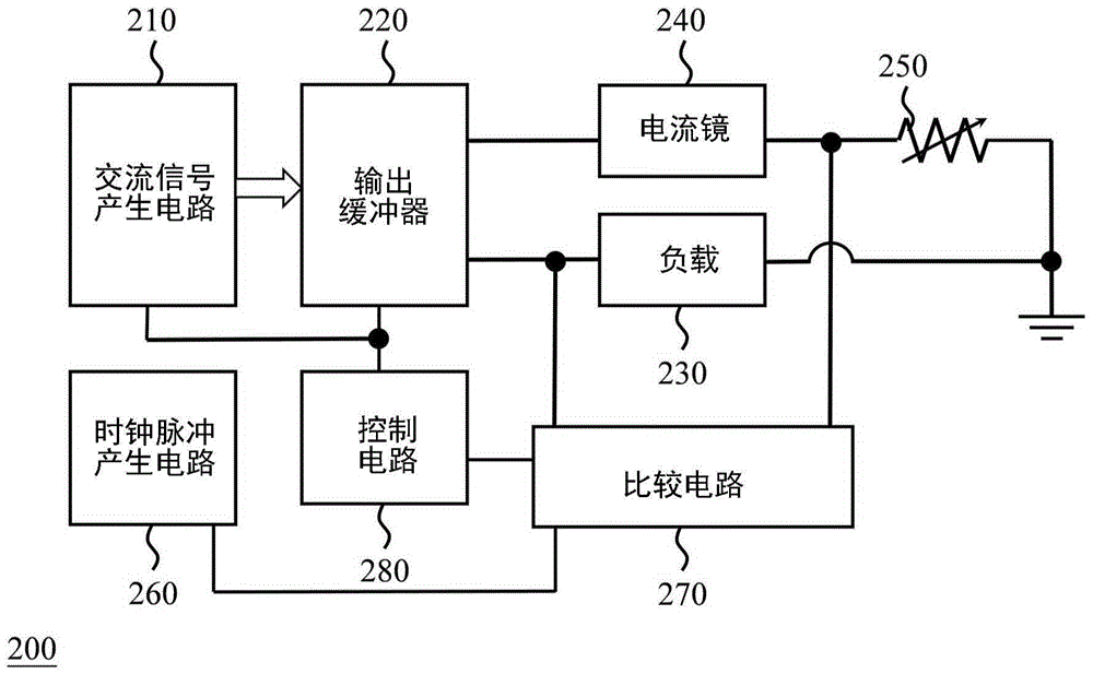
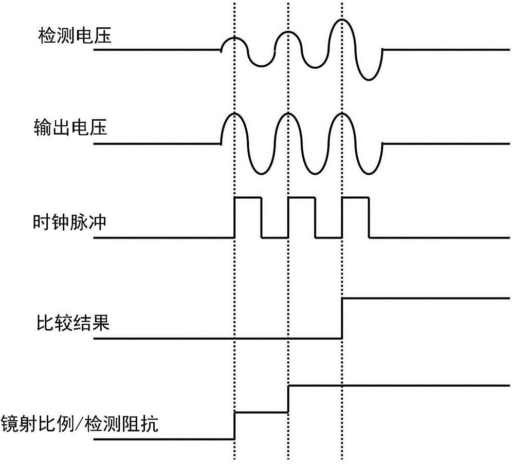
Disclosed are an impedance detection device and method which can detect the impedance of a load. In an embodiment, the impedance detection device comprises an alternating-current signal generation circuit, an output buffer, a current mirror, a detection impedor, a clock pulse generation circuit, a comparison circuit and a control circuit; the alternating-current signal generation circuit is used for providing an alternating-current signal; the output buffer is used for generating output voltage and output current according to the alternating-current signal and the impedance of the load; the current mirror is used for generating image current according to the output current; the detection impedor is used for generating detection voltage according to the image current; the clock pulse generation circuit is used for providing a clock pulse; the comparison circuit is used for comparing the output voltage with the detection voltage according to the clock pulse so as to generate a comparison result; the control circuit is coupled to the comparison circuit and at least one of the current mirror and the detection impedor and used for regulating at least one of the proportion between the image current and the output current and the impedance of the detection impedor according to the comparison result till the comparison result meets a preset condition. By the impedance detection device and method, abnormal sound can be avoided.

Description

technical field [0001] The invention relates to a detection device and method, in particular to an impedance detection device and method. Background technique [0002] Many existing consumer electronic devices provide one or more audio output holes for connecting one or more sound output devices, such as various types of earphones and speakers. However, sound output devices of different specifications can produce different output effects for the same sound signal, that is, the same sound signal may be moderately loud through the speaker output, but deafening through the earphone output; It's pleasant to listen to on headphone output, but suppresses distortion when output by another type of headphone. The above problems are mainly because the expected output impedance of the audio codec (Audio Codec) that outputs the sound signal (or the input impedance of the sound output device) does not match the actual situation, thus outputting a sound signal with too large or too small...

Claims


Application Information

Patent Timeline
Patent Type & Authority Applications(China)
IPC IPC(8): G01R27/02
Inventor 简志刚
Owner REALTEK SEMICON CORP
Why Eureka
Try Eureka