Dynamic load fast response circuit

A fast-response, dynamic-load technology, applied to electrical components, adjusting electrical variables, instruments, etc., can solve problems such as response speed that needs to be improved, and achieve the effect of quick response and reduction of deviation range

Active Publication Date: 2015-05-20
上海英联电子系统有限公司 +1
View PDF4 Cites 27 Cited by
  • Summary
  • Abstract
  • Description
  • Claims
  • Application Information

AI Technical Summary

Problems solved by technology

This scheme can effectively speed up the response speed and reduce the output voltage deviation range, but Rco/Cco still needs to be optimized for different output voltages and different outp

Method used


Image

  • Dynamic load fast response circuit
  • Dynamic load fast response circuit
  • Dynamic load fast response circuit

Examples


Embodiment Construction

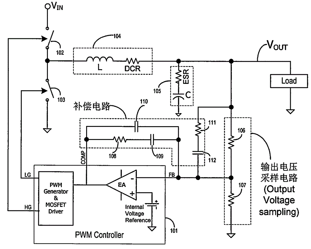
[0033] figure 1 It is a basic voltage-controlled Buck converter; 101 is a PWM control circuit, usually integrated with an error amplifier, a PWM generator, a MOSFET drive circuit, and other auxiliary function circuits such as a reference voltage source, soft start, oscillator, etc.; 102, 103 They are control switching tube and freewheeling switching tube, usually MOSFET; 104 is output filter inductor, which can be equivalent to ideal inductance and equivalent DC resistance in series; 105 is output filter capacitor, which can be equivalent to ideal capacitor and equivalent series Resistance composition; 106 and 107 are the voltage divider resistors for setting the output voltage, 106 is usually called the upper voltage divider resistor, and 107 is the lower voltage divider resistor; 108-112 and the internal error amplifier of the PWM controller form a compensation loop, which can be adjusted appropriately The compensation loop obtains Type-I, Type-II and Type-III control characte...


PUM


Abstract

The invention relates to a circuit for realizing fast dynamic load response by a Buck type DC/DC (direct current/direct current) converter. The load current change can be fast responded, and the output voltage deviation amplitude is reduced, so that the total required capacity of an outer capacitor is reduced. The circuit consists of a current sampling circuit, a signal processing circuit and a signal injection circuit, wherein the current sampling circuit consists of a sampling resistor or a resistance and capacitance series circuit connected with an output inductor in parallel, and for the second scheme, the other end of a capacitor is connected to the output voltage end. Voltage signals at two ends of the capacitor and the load current form the direct proportion, the signal processing circuit carries out amplification on direct current components and suppression on alternating current components in the voltage signals, the output of the signal processing circuit is injected into the negative feedback input end of a PWM (pulse width modulation) controller in an alternating current coupling mode by the signal injection circuit, the output duty ratio is forced to be fast regulated, the goals of fast response and small deviation oscillation amplitude are achieved, and the stability of the system steady work is not influenced. The circuit is also applicable to converters such as multi-phase Buck converters, normal shock converters, half-bridge converters and full-bridge converters.

Description

Technical field [0001] This patent relates to a circuit for a BUCK-type DC / DC converter to achieve fast dynamic load response. The circuit quickly responds to load current changes, reduces the deviation of the output voltage, and can reduce the total demand capacity of external energy storage capacitors. Background technique [0002] The topological structure of BUCK DC / DC converters is usually divided into non-isolated BUCK, forward, half bridge and full bridge types, which are widely used in various systems. Regardless of the type, the BUCK DC / DC converter topology includes an output filter circuit and a pulse width modulator (PWM-Pulse Width Modulator) control loop. The output filter circuit is composed of an inductor and a capacitor. Usually when the load current changes rapidly, due to the hysteresis effect of the output filter inductance and the control loop, the output voltage has a large deviation and it takes a long time to recover to the initial setting value. In order...

Claims


Application Information

Patent Timeline
IPC IPC(8): H02M1/08H02M3/155H02M3/335
CPCH02M3/156H02M3/33507H02M3/1566
Inventor 乔宗标
Owner 上海英联电子系统有限公司
Why Eureka
Try Eureka