
Surgical, torque-transmitting instrument including associated tool

A tool, surgical technology, applied in the direction of endoscopic cutting instruments, dentistry, couplings, etc.

Active Publication Date: 2015-05-20
AESCULAP AG
View PDF6 Cites 0 Cited by
  • Summary
  • Abstract
  • Description
  • Claims
  • Application Information

AI Technical Summary

Problems solved by technology

However, none of the known prior art suggests these provisions

Method used


Image

  • Surgical, torque-transmitting instrument including associated tool
  • Surgical, torque-transmitting instrument including associated tool
  • Surgical, torque-transmitting instrument including associated tool

Examples


Embodiment approach

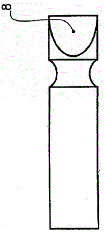
[0083] Figure 11 A preferred exemplary embodiment of such a tool mount 20 according to the invention is shown, the components of which are described in detail below and with respect to its cooperation with the tool 1 described at the outset.

[0084] First of all, the tool mount or tool lock 20 of the invention and according to a preferred exemplary embodiment of the invention comprises a radially inner tool receiving tube (hereinafter referred to as lead shaft) 22 which Comprising: a longitudinally slotted (beak-shaped) distal torque transfer portion and locking portion 24 at its distal end; in its slotted torque transfer zone 24a (see Figure 6 ), said portion 24 has an outer diameter adapted to the large-diameter tool shaft portion 6a and, in its adjoining locking zone 24b, an inner diameter adapted to the small-diameter tool shaft portion 6b. In this arrangement, the longitudinal slot 26 forms a slot width into which the tool shaft 1 can be inserted into the region of th...


PUM


Abstract

The invention relates to a surgical, torque-transmitting instrument comprising a preferably, universal handle to which a handle shaft with an inner torsion shaft or an inner tool shaft can be connected. Said torsion shaft can be connected by means of a plug coupling to a torque transmission path or drive inside the handle, said coupling consisting of an axially interlocking male and female coupling part. According to the invention, the cross-sectional shape of both coupling parts correspond approximately to a four-leaf clover.

Description

technical field [0001] The present invention relates to a surgical instrument for providing torque and a driven tool which is rotatably supported in an instrument handpiece or in a handpiece shaft connected to the instrument handpiece and which transmits the torque as high as possible to all Describe the driven tool. Background technique [0002] In advanced (minimally invasive) surgery, various instruments are used for fragment removal or material removal machining of e.g. Machining, the instrument includes an ergonomically shaped handpiece and optional replaceable tools (such as milling cutters, rotary knives, polishing heads, etc.) rotatably supported in the handpiece at a distance end so that it can be driven. Depending on the intended use and expected rotational speed, the tool drive is a hydraulic, pneumatic or electric drive that communicates with the The tools are operatively connected. The drive means can be integrated into the handpiece or realized as an extern...

Claims


Application Information

Patent Timeline
IPC IPC(8): A61B17/32A61B17/16F16D1/10
CPCA61B17/1622A61B17/32002A61B2017/0046A61B2017/00464A61B2017/320032F16D1/10F16D2001/102A61B17/162A61B17/1624A61B2017/00477A61B2017/00486A61B2017/1602A61C1/147F16D3/06
Inventor 于尔根·巴斯弗洛里安·卡夫特
Owner AESCULAP AG
Learn More