Method for manufacturing discharge lamp electrode

A manufacturing method and technology for discharge lamps, which are applied in the manufacture of discharge tubes/lamps, electrode systems, and thermionic cathodes, etc., can solve the problems of large joint surface application and electrode damage, and achieve the effect of excellent electrode performance.

Active Publication Date: 2015-05-20
ORC MFG +1
View PDF13 Cites 1 Cited by
  • Summary
  • Abstract
  • Description
  • Claims
  • Application Information

AI Technical Summary

Problems solved by technology

[0005] When electrodes are molded by solid-state bonding of different metal materials, due to the difference in thermal expansion coefficients, a large force may be applied to the bonding surface during lighting and the electrodes may be damaged.

Method used


Image

  • Method for manufacturing discharge lamp electrode
  • Method for manufacturing discharge lamp electrode
  • Method for manufacturing discharge lamp electrode

Examples


Embodiment 1

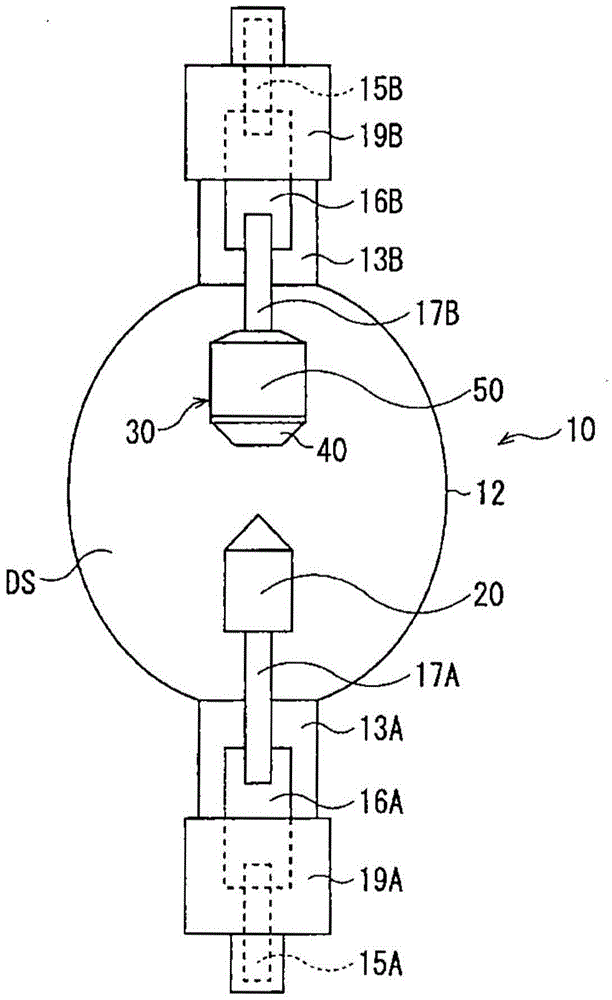
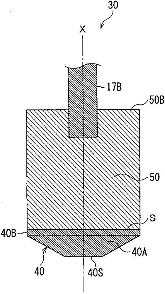
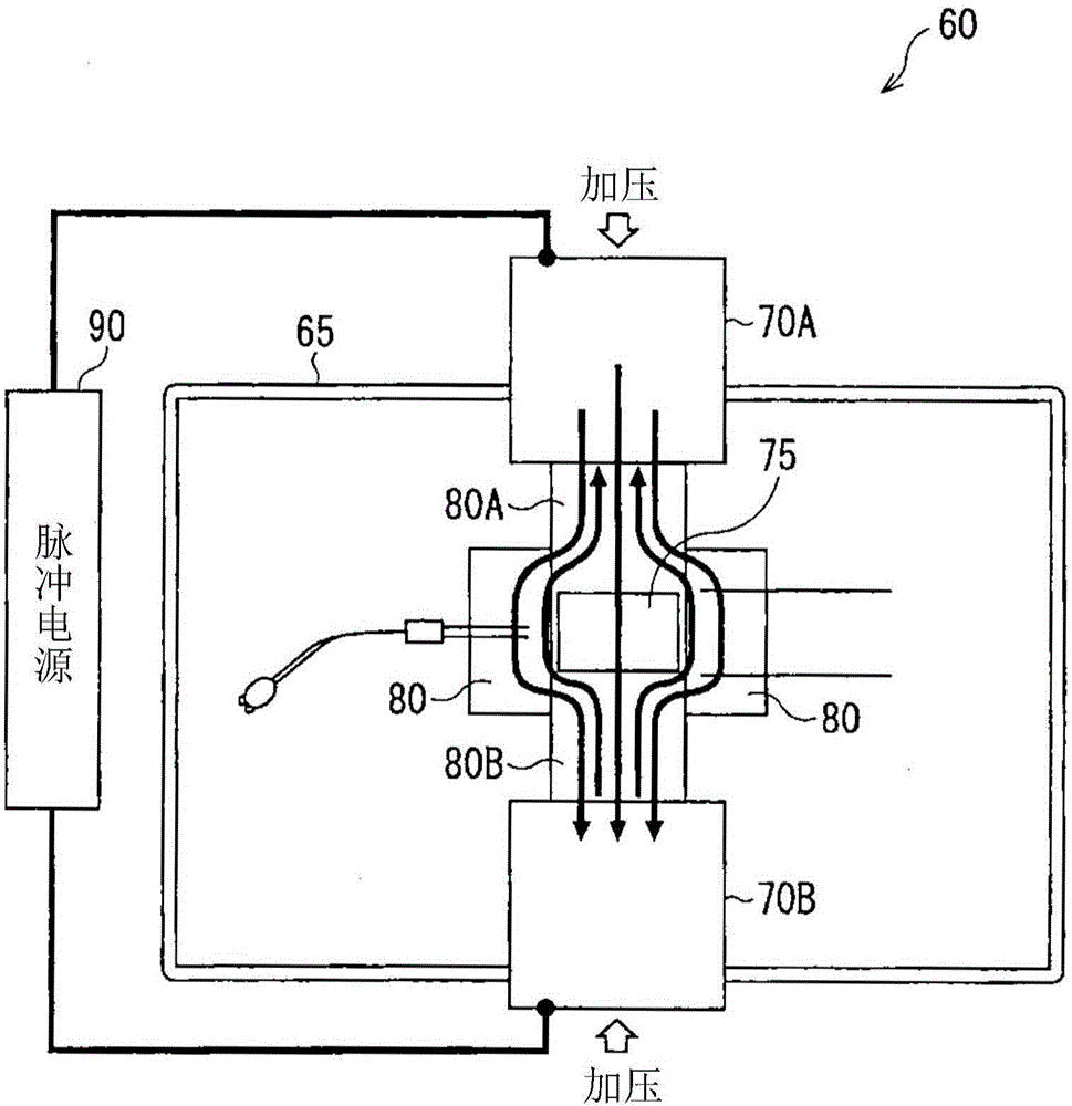
[0151] The discharge lamp of Example 1 corresponds to the discharge lamp of Embodiment 1. Regarding conditional expression (1), an anode in which a tip portion is a thoriated tungsten (thoriated tungsten) member and a main body portion is a pure tungsten member was manufactured by SPS bonding. At this time, the anodes of Examples 1 to 3 and Comparative Examples 1 to 3 were manufactured by changing the outer diameter L of the joining surface, the joining temperature T, the applied pressure P, and the joining time t. Then, a tensile test was performed on each of the manufactured anodes. Table 1 shows the experimental results.

[0152] [Table 1]

[0153]

[0154] Example 1 and Comparative Example 1 are electrodes manufactured by SPS-bonding a thoriated tungsten member and a pure tungsten member without intervening members. Example 2 and Comparative Example 2 are electrodes obtained by SPS bonding with a tantalum (Ta) member interposed therebetween as an insertion member. E...


PUM


Abstract

A method for manufacturing a discharge lamp electrode according to the present invention is a manufacturing method employing solid phase bonding, wherein a columnar tip solid member constituting at least a part of an electrode tip and containing an emitter, and a columnar body solid member constituting at least an electrode body and having a junction surface with a diameter larger than the diameter of the junction surface of the tip solid member are bonded by solid phase bonding via each junction surface, and machining is applied to an electrode material produced by the solid phase bonding so as to form a tapered electrode tip.

Description

technical field [0001] This invention relates to the discharge lamp used for an exposure apparatus etc. Especially, It is related with the manufacturing method of the electrode for discharge lamps which joined several members. Background technique [0002] In discharge lamps, electrodes are formed by joining members with different metal types, crystal properties, etc. as the output becomes higher. For example, a metal member containing an emitter such as thorium is used as an electrode tip portion, and a refractory metal member such as pure tungsten is used as a main body, and the two metal members are joined to each other. [0003] Diffusion bonding, which is one of solid-phase bonding, is known as a bonding method. In diffusion bonding, the crystal structure can be tilted in the axial direction or the metal crystal grains can be bonded in the vicinity of the bonding surface without deforming the metal crystal grains in the axial direction, so that the degradation of elect...

Claims


Application Information

Patent Timeline
Patent Type & Authority Applications(China)
IPC IPC(8): H01J9/02H01J61/06H01J61/073
CPCG03F7/70016H01J9/02H01J9/04H01J61/0732H01J61/0735H01J61/86
Inventor 早川壮则馆林和人芹泽和泉小平宏石锅荣彦本多友彦古畑肇小松丰泷泽秀一
Owner ORC MFG
Why Eureka
Try Eureka