
Near sound field ultrasonic reactor

An ultrasonic and reactor technology, applied in the field of near-sound field ultrasonic reactors, can solve the problems of limited service life of parallel plates, uneven ultrasonic field, poor compatibility, etc., to improve utilization efficiency, small footprint, powerful effect

Active Publication Date: 2015-05-27
山东润蒙应急救援装备有限公司
View PDF4 Cites 6 Cited by
  • Summary
  • Abstract
  • Description
  • Claims
  • Application Information

AI Technical Summary

Problems solved by technology

However, this kind of reactor is not very compatible with other equipment in the field application, and it occupies a large area, and uses more transducers, which increases the failure points. In addition, the service life of the parallel plate is limited
The ultrasonic field of the reactor is not uniform due to the structure of the rectangular channel of the reactor. There are many weak and dead corners of cavitation in the reaction field, and there is the problem of uneven ultrasonic cavitation. In the large-scale continuous production process, it may There will be unstable product quality
In addition, in terms of effective utilization of ultrasonic energy, there are also cases where only the energy on one side of the ultrasonic radiation surface is used, while the energy on the other side is not utilized.

Method used


Image

  • Near sound field ultrasonic reactor
  • Near sound field ultrasonic reactor
  • Near sound field ultrasonic reactor

Examples


Embodiment Construction

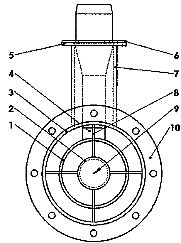
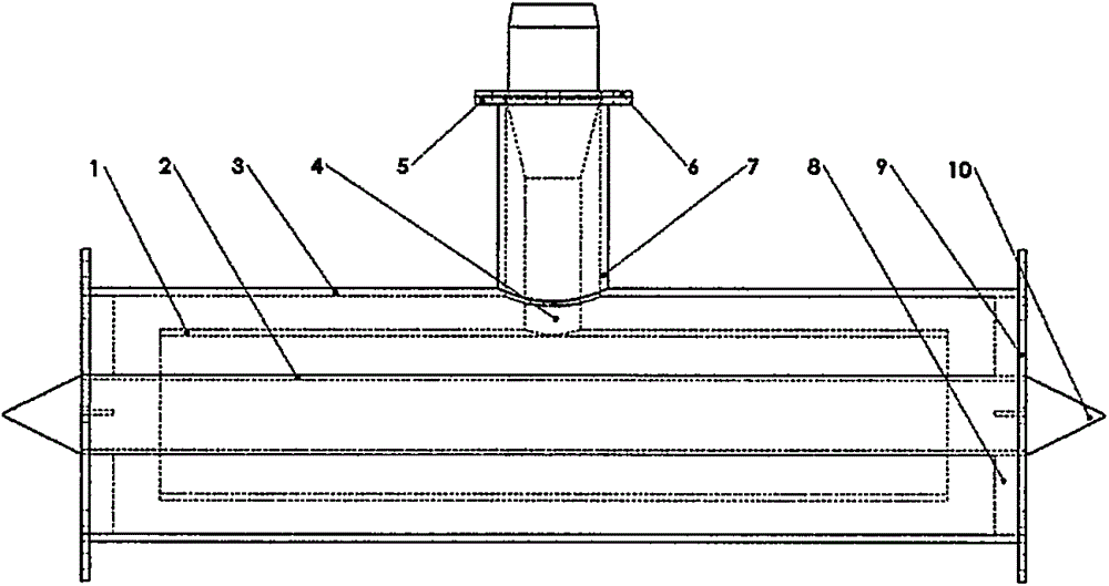
[0036] see figure 1 with figure 2 , which is a schematic structural view of Embodiment 1 of a near-acoustic field ultrasonic reactor of the present invention. Such as figure 1 with figure 2 As shown: it includes ultrasonic vibration tube 1, ultrasonic internal reflection tube 2, ultrasonic external reflection tube 3, ultrasonic horn 4, connecting ultrasonic horn flange 5, ultrasonic horn flange 6, fixed horn sleeve Tube 7, fixed internal reflection tube rib 8, internal reflection tube splitter cone 9, and outer reflection tube flange 10. Among them, the ultrasonic vibrating tube 1 is the core component, and its material can be ordinary metal materials, or titanium alloys, alloys, stainless steel, aluminum alloys, copper and other metal materials according to different working fluids for ultrasonic treatment. The ultrasonic vibrating tube 1 and the ultrasonic horn 4, the ultrasonic transducer and the ultrasonic drive power supply are connected in sequence to form a comple...


PUM


Abstract

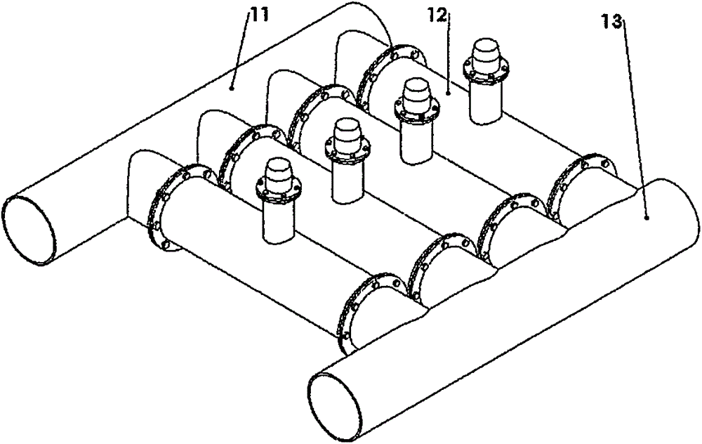
The invention relates to the technical field of generation and transfer of ultrasonic vibration and particularly relates to a near sound field ultrasonic reactor which efficiently uses ultrasonic energies. The near sound field ultrasonic reactor comprises an ultrasonic vibration tube, an ultrasonic internal reflection tube, an ultrasonic external reflection tube, an ultrasonic amplitude transformer, a flange connected with the ultrasonic amplitude transformer, an ultrasonic amplitude transformer flange, a fixed amplitude transformer sleeve, a fixed internal reflection tube rib, an internal reflection tube dividing conehead, an external reflection tube flange and the like. The ultrasonic reactor provided by the utility model is the near sound field ultrasonic reactor which is simple in structure, free from maintenance in operation, high in utilization ratio of ultrasonic energy, large in ultrasonic radiating area, uniform in ultrasonic sound intensity, low in power consumption and energy-saving and environmentally friendly and efficiently uses ultrasonic energies. The near sound field ultrasonic reactor provided by the utility model not only effectively utilizes radiating energies on the internal and external faces of the ultrasonic vibrating tube, but also effectively utilizes radiating energies reflected from inner and outer sides, so that the near sound field ultrasonic reactor is suitable for industrial flows in continuous production. A common plate type ultrasonic reactor is not as good as the near sound field ultrasonic reactor.

Description

technical field [0001] The invention relates to the technical field of generation and transmission of ultrasonic vibrations, in particular to a near-sound-field ultrasonic reactor that utilizes ultrasonic energy efficiently. Background technique [0002] With the development of ultrasonic technology, sonochemistry began to form as a new branch of chemistry. The emergence of sonochemistry has attracted the attention of many advanced countries and invested manpower and material resources in research. Due to the vibration of medium particles caused by ultrasonic waves, it can generate great speed and acceleration, and can transmit a large amount of energy to medium particles. When propagating in liquid, it can produce cavitation effect, activation effect, polymerization effect, shear effect, mechanical thermal effect, etc. A series of physical effects, so that the ultrasonic has the functions of dispersing, pulverizing, activating, etc., which can make the reaction process onl...

Claims


Application Information

Patent Timeline
IPC IPC(8): B01J19/10
CPCB01J19/10B01J2219/00932
Inventor 褚兴全褚兴国王超马秀英胡薇
Owner 山东润蒙应急救援装备有限公司
Learn More