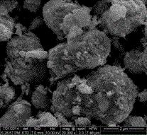
Preparation method and application of graded-structure BiOI/Bi2MoO6 composite visible light catalyst
A hierarchical structure, visible light technology, applied in the field of environmental pollution control, can solve the problem of low electron/hole separation efficiency, achieve excellent visible light catalytic degradation activity, easy preparation process, and improved degradation efficiency
- Summary
- Abstract
- Description
- Claims
- Application Information
AI Technical Summary
Problems solved by technology
Method used
Image
Examples
Embodiment 1
[0020] Example 1 Bi 2 MoO 6 Preparation of microspheres
[0021] Synthesis of Bi by solvothermal method 2 MoO 6 Microspheres, weighing 0.485 g Bi(NO 3 ) 3 ·5H 2 O was added to 10 mL of ethylene glycol solution, ultrasonically dispersed, and completely dissolved into a transparent solution; 60 mL of absolute ethanol was slowly added to the transparent solution, magnetically stirred, and 0.0618 g (NH 4 ) 6 Mo 7 o 24 4H 2 O, magnetic stirring to dissolve completely; move it to a 100 mL autoclave, and react at 140 °C for 16 h; after the autoclave gradually cools down to room temperature, centrifuge to precipitate, and wash with ethanol and deionized water for 3 The second time, the product was placed in an oven at 60 °C for 6 h.
Embodiment 2
[0022] Example 2 Bi 2 MoO 6 Preparation of microspheres
[0023] Synthesis of Bi by solvothermal method 2 MoO 6 Microspheres, weighing 0.97 g Bi(NO 3 ) 3 ·5H 2 O was added to 20 mL of ethylene glycol solution, ultrasonically dispersed to make it completely dissolved into a transparent solution; 50 mL of absolute ethanol was slowly added to the transparent solution, magnetically stirred, and 0.1236 g (NH 4 ) 6 Mo 7 o 24 4H 2 O, magnetic stirring to make it completely dissolved; move it to a 100 mL autoclave, and react at 160 °C for 12 h; after the autoclave gradually cooled to room temperature, centrifuge to precipitate, wash with ethanol and deionized water for 3 The second time, the product was placed in an oven at 70 °C for 5 h.
Embodiment 3
[0024] Example 3 Bi 2 MoO 6 Preparation of microspheres
[0025] Synthesis of Bi by solvothermal method 2 MoO 6Microspheres, weighing 1.455 g Bi(NO 3 ) 3 ·5H 2 O was added to 30 mL of ethylene glycol solution, ultrasonically dispersed, and completely dissolved into a transparent solution; 40 mL of absolute ethanol was slowly added to the transparent solution, magnetically stirred, and 0.1854 g (NH 4 ) 6 Mo 7 o 24 4H 2 O, magnetic stirring to dissolve completely; move it to a 100 mL autoclave, and react at 180 °C for 10 h; after the autoclave gradually cools down to room temperature, centrifuge to precipitate, and wash with ethanol and deionized water for 3 The second time, the product was placed in an oven at 80 °C for 4 h.
PUM
| Property | Measurement | Unit |
|---|---|---|
| wavelength | aaaaa | aaaaa |
Abstract
Description
Claims
Application Information
 - R&D
- Intellectual Property
- Life Sciences
- Materials
- Tech Scout
- Unparalleled Data Quality
- Higher Quality Content
- 60% Fewer Hallucinations
Browse by: Latest US Patents, China's latest patents, Technical Efficacy Thesaurus, Application Domain, Technology Topic, Popular Technical Reports.
© 2025 PatSnap. All rights reserved.Legal|Privacy policy|Modern Slavery Act Transparency Statement|Sitemap|About US| Contact US: help@patsnap.com

