

Automatic lost foam pattern curtain-coating device and method
A lost foam and automatic technology, applied in the direction of casting molding equipment, casting molds, cores, etc., can solve the problems of physical and mental health of workers, low degree of automation, poor working environment, etc., to ensure physical and mental health, high degree of automation, improve efficiency effect
- Summary
- Abstract
- Description
- Claims
- Application Information
AI Technical Summary
Problems solved by technology
Method used
Image

Examples
Embodiment Construction
[0032] In order to make the technical means, creative features, goals and effects achieved by the present invention easy to understand, the present invention will be further elaborated below.
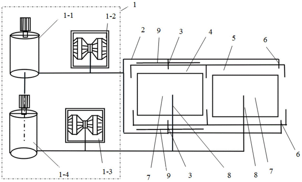
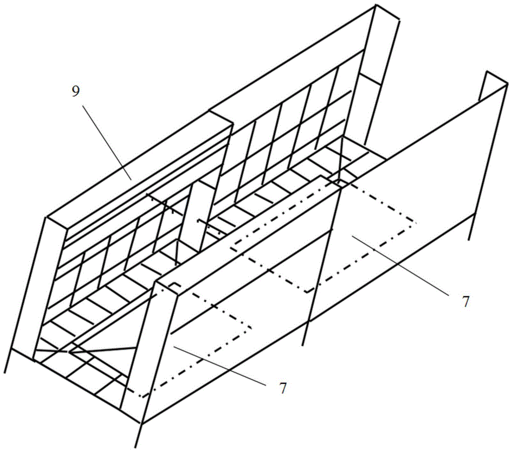
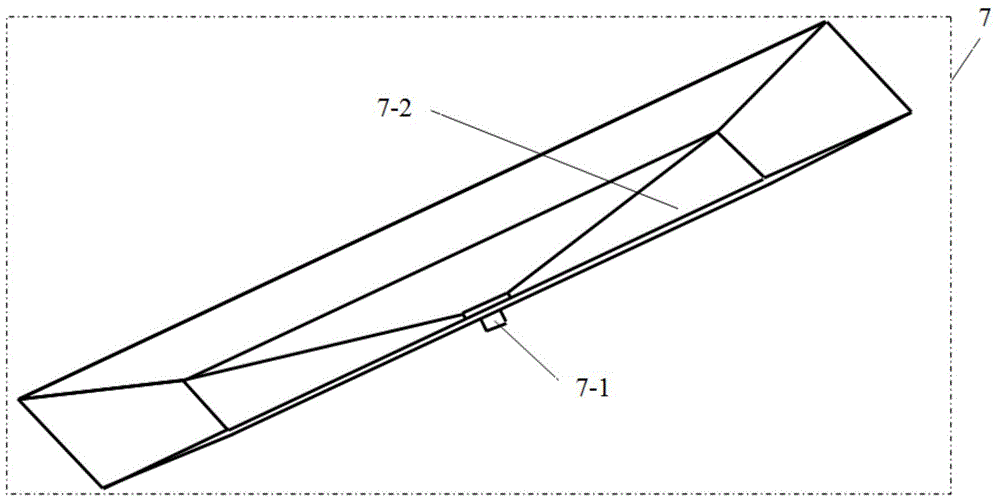
[0033] Such as Figure 1 to Figure 9As shown, an automatic shower coating device for lost foam white molds, including a paint supply device 1, a feed pipe 2, an automatic shower joint 3, an automatic shower room 4, a manual shower room 5, a spray gun 6, and a shower pool 7 , return material pipeline 8 and automatic shower coating equipment 9, described automatic shower coating equipment 9 is installed in the automatic shower coating room 4, and described spray gun 6 is installed in the artificial shower room 5, and described coating supply device 1 passes through feeding The pipeline 2 is correspondingly connected with the automatic shower joint 3 and the spray gun 6, the automatic shower joint 3 is connected with the automatic shower equipment 9, and the shower pool 7 is respectively i...
PUM
 Abstract
Description
Claims
Application Information