Cutter, Device And Method For Manufacturing Cutter

A technology for manufacturing devices and knives, which is applied in the field of improving the structure of knives, and can solve the problems of increased cutting resistance, easy damage, and easy damage

Inactive Publication Date: 2015-05-27
COLOSSAL CAREER MACHINERY
View PDF6 Cites 1 Cited by
  • Summary
  • Abstract
  • Description
  • Claims
  • Application Information

AI Technical Summary

Problems solved by technology

[0003] 1. Time-consuming: After the tool is milled by the CNC milling machine, it is necessary to use the conical forming knife to perform time-consuming pick-up work, but because the sharp point of the conical forming knife does not have any cutting force, therefore, after processing There will still be "triangular-like triangles with curved edges" remaining at the corners of the cutting blades
[0004] 2. Strenuous and fragile: the sharpness of the knife edge at the remaining material is relatively low, so that the cutting resistance is relatively increased. Therefore, a greater pressure must be applied to the knife wheel to remove the material (dressing) corresponding to the remaining material. or patch) to cut off, so that the blade part bears greater pressure and is easy to be damaged, thereby shortening the service life of the tool
[0005] 3. Finished product defects: When the triangular-like residual material at the angle of the cutting blade is not completely removed, it will affect the cutting effect of the tool, so that when the tool is cutting, the product material corresponding to the residual material at the angle of the cutting blade (Dressing or patch) has flocks on the edges, which affects the quality of the finished product

Method used


Image

  • Cutter, Device And Method For Manufacturing Cutter
  • Cutter, Device And Method For Manufacturing Cutter
  • Cutter, Device And Method For Manufacturing Cutter

Examples


Embodiment Construction

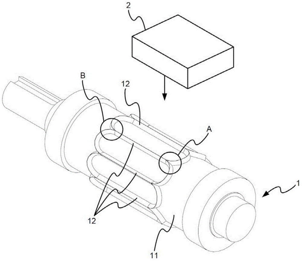
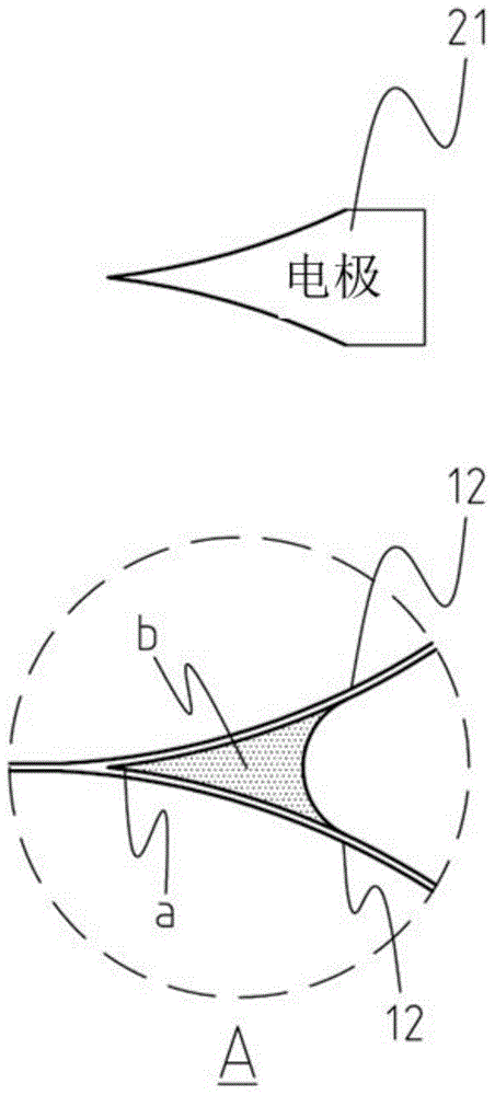
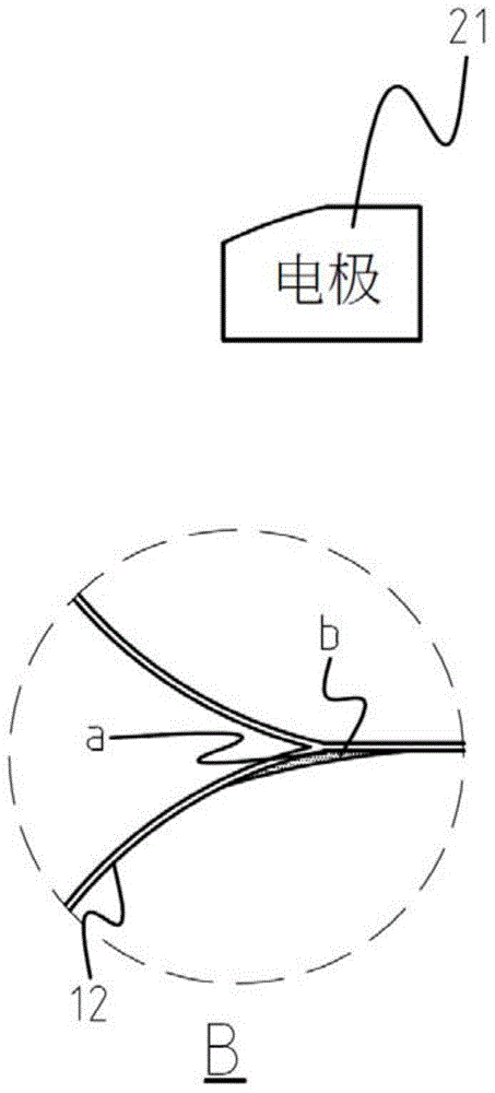
[0024] see figure 1 , figure 2 , image 3 , Figure 4 and Figure 5 as shown, figure 1 It is a schematic diagram of the present invention. The present invention is a cutter for manufacturing medical dressings and patches and its manufacturing device and method. The cutter 1 includes a cutter wheel body 11, and a plurality of cutting blades 12 formed by processing the cutter wheel body 11. In the illustration of this embodiment, there are a plurality of adjacent cutting blades 12, but the present invention does not limit the plurality of cutting blades 12 to be adjacent to each other or not, and no matter whether it is one cutting blade, multiple phases Adjacent or non-adjacent cutting blades are suitable for the manufacturing apparatus and method of the present invention. The cutting tool manufacturing device includes an electrical discharge machining mechanism 2 corresponding to the cutting tool 1 . figure 2 for the invention figure 1 The enlarged schematic diagram o...


PUM


Abstract

The present invention relates to a cutter for making medical dressing and patch, and a device and a method for manufacturing the cutter. The cutter comprises a cutter wheel body, a or a plurality of cutting blades processed on the cutter wheel body, wherein the inner sides or outer sides of the cutting blades possess the included angles. The device for manufacturing the cutter comprises an electric spark processing mechanism corresponding to the cutting blades of the above cutter and used for processing the excess materials at the included angles of the cutting blades, and the method for manufacturing the cutter comprises the step of manufacturing the cutting blades in a milling machine processing way controlled by the computer numerical values, and the excess materials at the included angles are removed in an electric spark processing manner, so that the precise sharp corners are corrected, and the cutting blades are formed on the cutter wheel body at the integral and consistent sharpness.

Description

technical field [0001] The invention relates to an improved cutter structure for manufacturing medical dressings and patches, in particular to a cutter structure with a precision blade angle made by an electric discharge machining device. Background technique [0002] Generally, the cutting tools used to make medical dressings or patches are manufactured by computer numerical control (Computer Numerical Control, CNC) milling machine processing, and after the cutting blade is made on the cutter wheel body, the shape of the cutting blade There will be residual "triangle-like" material at the included corner, so it is necessary to use a tapered forming knife to perform post-processing on the aforementioned residual material to remove it. Yet with above-mentioned traditional knife manufacture, it has following shortcoming at least: [0003] 1. Time-consuming: After the tool is milled by the CNC milling machine, it is necessary to use the conical forming knife to perform time-co...

Claims


Application Information

Patent Timeline
Patent Type & Authority Applications(China)
IPC IPC(8): B23P15/00B26F1/44D06H7/00
CPCB23H1/00B23P15/28B26F1/44D06H7/00
Inventor 吕福雄
Owner COLOSSAL CAREER MACHINERY
Why Eureka
Try Eureka