Active control method of milling chatter vibration based on electric spindle of magnetic suspension bearing

A technology of magnetic suspension bearing and milling chatter, which can be used in automatic control devices, manufacturing tools, metal processing equipment, etc., and can solve the problems of reduced workpiece surface quality and low milling efficiency.

Active Publication Date: 2015-05-27
HUAZHONG UNIV OF SCI & TECH
View PDF6 Cites 19 Cited by
  • Summary
  • Abstract
  • Description
  • Claims
  • Application Information

AI Technical Summary

Problems solved by technology

[0005] In view of the defects of the prior art, the purpose of the present invention is to provide an active control method for milling chatter vibration based on magnetic suspension bearing electric spind...

Method used


Image

  • Active control method of milling chatter vibration based on electric spindle of magnetic suspension bearing
  • Active control method of milling chatter vibration based on electric spindle of magnetic suspension bearing
  • Active control method of milling chatter vibration based on electric spindle of magnetic suspension bearing

Examples


Embodiment Construction

[0031] In order to make the object, technical solution and advantages of the present invention clearer, the present invention will be further described in detail below in conjunction with the accompanying drawings and embodiments. It should be understood that the specific embodiments described here are only used to explain the present invention, not to limit the present invention.

[0032] The specific embodiments of the present invention will be further described below in conjunction with the accompanying drawings. It should be noted here that the descriptions of these embodiments are used to help understand the present invention, but are not intended to limit the present invention. In addition, the technical features involved in the various embodiments of the present invention described below can be combined with each other as long as they do not constitute a conflict with each other.

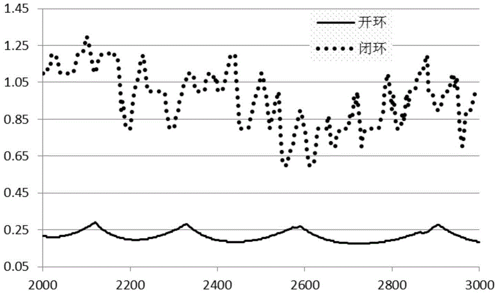
[0033] In actual milling, for any specified spindle speed Ω, when the axial depth of cut...


PUM


Abstract

The invention discloses an active control method of milling chatter vibration based on an electric spindle of a magnetic suspension bearing. The method comprises the following steps: collecting a current displacement signal generated when the electric spindle has the milling chatter vibration; obtaining a state vector Q(t) formed by the displacement of the electric spindle and the speed; obtaining harmonic displacement which is shown as the formula in the description according to the electric spindle displacement [Fx Fy]T and a trigonometric function column vector phi(t); obtaining a first self-adaptive weight coefficient which is shown as the formula in the description and a second self-adaptive weight coefficient which is shown as the formula in the description; obtaining a first self-adaptive rate K1 and a second self-adaptive rate K2 according to the harmonic displacement h(t), the first self-adaptive weight coefficient lambda1 and a second self-adaptive weight coefficient lambda2; obtaining self-adaptive control current which is shown as the formula in the description according to the first self-adaptive rate K1, the second self-adaptive rate K2 and the harmonic displacement h(t); and applying the self-adaptive control current Qc(t) on a radial magnetic suspension bearing and generating corresponding magnetic field force so as to restrain the chatter vibration of the spindle. Through the active control method, the chatter vibration in the milling process is eliminated, thereby ensuring the processing quality and improving the processing efficiency.

Description

technical field [0001] The invention belongs to the technical field of numerical control machining, and more specifically relates to an active control method for milling chatter vibration based on a magnetic suspension bearing electric spindle. Background technique [0002] In terms of chatter suppression in five-axis CNC machining of complex curved surface parts, the traditional method is mainly based on passive control. The system works below the lobe effect point, so as to obtain high speed and depth of cut under the premise of ensuring milling stability. Although the design and installation of the passive control method is simple, the stable range it can adjust is very small, and the improvement of the closed-loop dynamics is limited. Therefore, it is necessary to adopt a control method that changes the inherent dynamic characteristics of the spindle unit to suppress the flutter. This control method is based on the active control technology of the magnetic suspension be...

Claims


Application Information

Patent Timeline
IPC IPC(8): B23Q15/12
CPCB23Q15/12
Inventor 陈智勇吴越赵欢张海涛赵杰丁汉赵鑫张国强
Owner HUAZHONG UNIV OF SCI & TECH
Why Eureka
Try Eureka