
Turbine-type aeration machine

An aerator and turbine-type technology, applied in the field of aerator, can solve the problems of complex structure and low work efficiency, and achieve the effects of simplifying structure, improving work efficiency, improving oxygen transfer efficiency and oxygenation capacity

Inactive Publication Date: 2015-05-27
天津玉清水产科技发展有限公司
View PDF0 Cites 5 Cited by
  • Summary
  • Abstract
  • Description
  • Claims
  • Application Information

AI Technical Summary

Problems solved by technology

The structure of traditional aerators is mostly complicated, and the work efficiency is not high, so there is a lot of room for improvement

Method used


Image

  • Turbine-type aeration machine

Examples


Embodiment Construction

[0012] The present invention will be further described below in conjunction with accompanying drawing.

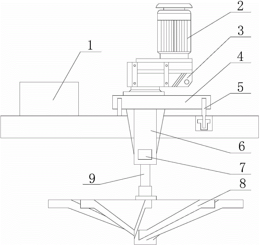
[0013] Such as figure 1 As shown, a turbine aerator of the present invention includes a controller (1), a motor (2), a frame (4), a height adjustment device (5), a main shaft (9) and an impeller (8), and the controller The control signal output terminal of (1) is connected to the control signal input terminal of the motor (2), the frame (4) is connected to the ground on the pool through the height adjustment device (5), and the lower part of the motor (2) is provided with a reduction box ( 3), the rotating shaft of the motor (2) is connected to the main shaft (9) through the reduction box (3), the lower end of the main shaft (9) is connected to the impeller (8), and the impeller (8) is located under the water surface in the pool.

[0014] A turbine aerator also includes an inverted umbrella seat (6), the main shaft (9) is arranged in the inverted umbrella seat (6), and the...


PUM


Abstract

The invention discloses a turbine-type aeration machine, which comprises a controller, a motor, a frame, a height adjusting device, a main shaft and an impeller, a control signal output end of the controller is connected to the control signal input end of the motor, the frame is connected to the ground on a pool through the height adjusting device, a reduction box is arranged at lower part of the motor, the rotating shaft of the motor is connected to a main shaft in a transmission mode through the reduction box, the lower end of the main shaft is connected to the impeller, and the impeller is positioned under the water surface in the pool. The turbine-type aeration machine employs an inverted motor to provide the rotation power to the impeller, aeration machine structure is greatly simplified, the inverted umbrella-type impeller is employed so that oxygen in air can be fully dissolved and absorbed, oxygen transfer efficiency and oxygen charging capability are increased, so that work efficiency of a whole aeration machine is increased.

Description

【Technical field】 [0001] The invention relates to an aerator, in particular to a turbo aerator. 【Background technique】 [0002] The aerator injects "micro-bubbles" directly into the untreated sewage through the diffuser impeller. Under the joint action of the coagulant and flocculant, the suspended solids undergo physical and chemical flocculation, thereby forming large suspended solids. The floc, under the action of the buoyancy of the bubble group, the "floc" floats to the liquid surface to form scum, which is separated from the water by a scum scraper; there is no need to clean the nozzle, and no clogging will occur. During operation, the impeller of the water pump rotates at a high speed driven by the submersible motor, pushing the mud-water mixture into the ejector to form a jet, and a negative pressure area is generated around the jet, and the air is sucked into the negative pressure area of ​​the jet nozzle through the suction pipe, and in the throat of the ejector T...

Claims


Application Information

Patent Timeline
Patent Type & Authority Applications(China)
IPC IPC(8): C02F7/00
CPCC02F7/00C02F2201/002Y02W10/10
Inventor 谢富国
Owner 天津玉清水产科技发展有限公司
Learn More