Variable radius spiral ladder spillway

A flood discharge tunnel and variable radius technology, which is applied in the field of flood discharge tunnels with high hydraulic parameters, can solve the problems of high flow velocity at the tail of the tunnel and water outlet, difficult energy dissipation in the downstream arrangement, and easy damage to the flood discharge and energy dissipation facilities. The length of the cave body, the improvement of project economy, and the effect of eliminating cavitation and cavitation

Inactive Publication Date: 2016-08-24
SICHUAN UNIV
View PDF5 Cites 0 Cited by
  • Summary
  • Abstract
  • Description
  • Claims
  • Application Information

AI Technical Summary

Problems solved by technology

However, for topographic and geological conditions where the river valley is V-shaped or narrow, and the mountains on both sides are steep, the layout of the traditional straight line or multi-segment straight line and arc-connected flood discharge tunnel will not be able to fully dissipate energy during the flow process due to the short body of the tunnel. , resulting in relatively high flow velocity at the tail of the tunnel and at the outlet of the water flow, difficulty in arranging energy dissipation downstream and endangering the safety of the river, etc.
However, when the steep trough spillway is directly built, there are also problems such as the high flow velocity downstream and at the end of the steep trough, and the downstream flood discharge and energy dissipation facilities are easily damaged.

Method used


Image

  • Variable radius spiral ladder spillway
  • Variable radius spiral ladder spillway
  • Variable radius spiral ladder spillway

Examples


Embodiment 1

[0030] The engineering overview of embodiment 1 and comparative example 1 is as follows:

[0031] A power station is built in a V-shaped valley, with steep mountains on both sides and complex geological and topographical conditions. It is required that the entrance elevation of the flood discharge tunnel is 1061m, the exit elevation is 951m, the drop is 110m, and the flood discharge flow is 420m 3 / s.

[0032] Aiming at the above-mentioned projects, hydraulic model tests of two kinds of spillway layouts in Example 1 and Comparative Example 1 were carried out:

[0033] Example 1

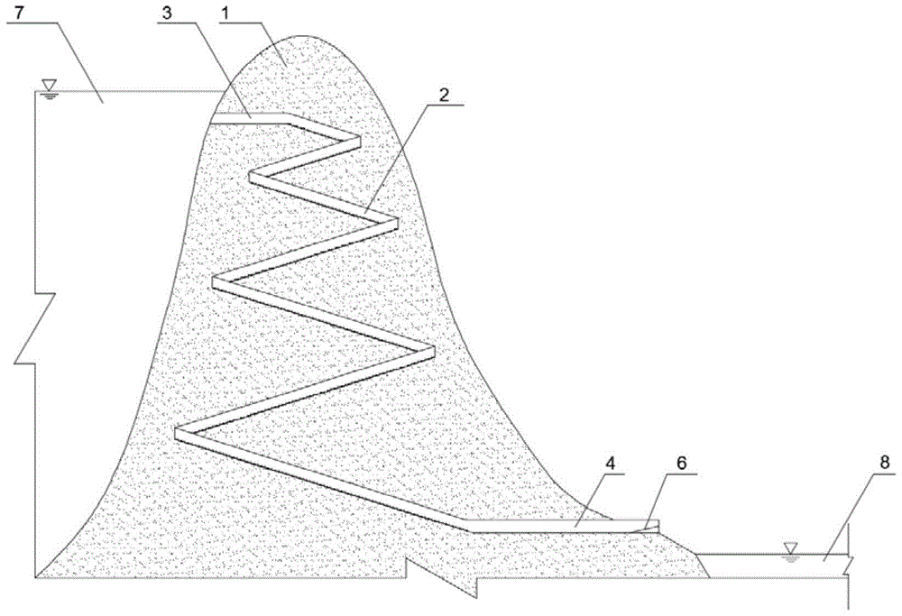
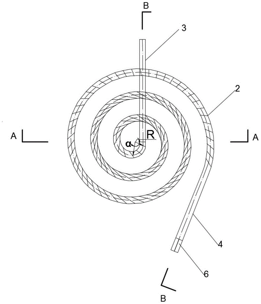
[0034] In this embodiment, a variable-radius spiral ladder flood discharge tunnel is used, and the structure is as follows figure 1 , 2 As shown in . It is connected with the upstream aqueduct 3 that introduces the water in the reservoir into the flood discharge tunnel, and the downstream end of the variable-radius spiral stepped flood discharge tunnel is connected with the downstream aqueduct 4 t...

Embodiment 2

[0039] The engineering overview of embodiment 2 and comparative example 2 is as follows:

[0040] A power station is built in a V-shaped valley, with steep mountains on both banks and a narrow and wide mountain downstream. The entrance elevation of the flood discharge tunnel is 746m, the exit elevation is 606m, the drop is 140m, and the flood discharge flow is 300m 3 / s. Aiming at the above-mentioned projects, hydraulic model tests of two kinds of flood discharge facility layouts in Example 2 and Comparative Example 2 were carried out.

[0041] Example 2

[0042]In this embodiment, a variable-radius spiral ladder flood discharge tunnel is used. The flood discharge tunnel is arranged in the mountain body 1 on the side of the reservoir dam body. The upstream end of the stepped flood discharge tunnel is connected with the upstream channel 3 that introduces the water in the reservoir into the flood channel, and the downstream end of the variable-radius spiral stepped flood chann...

Embodiment 3

[0047] The engineering overview of embodiment 3 and comparative example 3 is as follows:

[0048] A power station is built in a narrow river valley, with steep mountains on both sides and deep river coverage in the downstream. The entrance elevation of the flood discharge tunnel is 861m, the exit elevation is 701m, the drop is 160m, and the flood discharge flow is 600m 3 / s. Aiming at the above-mentioned projects, the hydraulic model tests of two kinds of spillway tunnel layouts in Example 3 and Comparative Example 3 were carried out.

[0049] Example 3

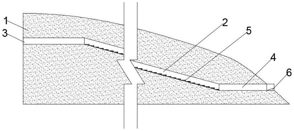
[0050] In this embodiment, a variable-radius spiral ladder flood discharge tunnel is used, and the structure is as follows figure 1 , 2 , 3, and 4, the flood discharge tunnel 2 is set in the mountain body 1 on the side of the reservoir dam body, the upstream end of the variable radius spiral ladder flood discharge tunnel is located at the upper part of the mountain body 1, and the downstream end is located at the lower par...


PUM


Abstract

The invention discloses a variable-radius spiral stepped flood discharge tunnel, which is arranged in a mountain at the side of a reservoir dam; the upstream end of the variable-radius spiral stepped flood discharge tunnel is located in the upper part of the mountain, the downstream end of the upstream end of the variable-radius spiral stepped flood discharge tunnel is located in the lower part of the mountain, the bottom surface of the variable-radius spiral stepped flood discharge tunnel is of a stepped structure, the upstream end of the variable-radius spiral stepped flood discharge tunnel is connected with an upstream diversion conduit for diverting water in a reservoir into the flood discharge tunnel, and the downstream end of the variable-radius spiral stepped flood discharge tunnel is connected with a downstream diversion conduit for diverting the water in the flood discharge tunnel into a downstream riverway. The variable-radius spiral stepped flood discharge tunnel disclosed by the invention can decrease the flow velocity at the outlet of the flood discharge tunnel, prevent cavitation damage, increase the energy dissipation efficiency and ensure the safety of the downstream riverway.

Description

technical field [0001] The invention belongs to the technical field of energy dissipation in water conservancy and hydropower projects, and in particular relates to a flood discharge tunnel for high hydraulic parameters. Background technique [0002] High dam flood discharge and energy dissipation is an important technology to ensure flood control of large-scale water conservancy projects. Traditional high dam flood discharge and energy dissipation usually use a straight line or a multi-segment straight line and a circular arc to connect the spillway, or directly build a steep groove spillway to dissipate energy. However, for topographic and geological conditions where the valley is V-shaped or narrow, and the mountains on both sides are steep, the arrangement of traditional straight lines or multi-segment straight lines and arc-connected flood discharge tunnels will not be able to fully dissipate energy during the flow process due to the short body of the tunnel. , resulti...

Claims


Application Information

Patent Timeline
Patent Type & Authority Patents(China)
IPC IPC(8): E02B8/06
CPCE02B8/06
Inventor 许唯临张建民何小泷彭勇刘善均王韦邓军曲景学田忠张法星周茂林
Owner SICHUAN UNIV
Why Eureka
Try Eureka