Waterproof and drainage structure of vertical shaft in underground workhouse and construction method for waterproof and drainage structure

A technology for underground powerhouses and construction methods, applied in underwater structures, infrastructure engineering, water conservancy projects, etc., can solve the problems of blind ditch being easily blocked, failure of drainage, unsatisfactory drainage effect, high construction cost, etc., and achieve waterproof and anti-seepage effects Good, strong water seepage effect, convenient construction

Inactive Publication Date: 2015-05-27
CHINA POWER CONSRTUCTION GRP GUIYANG SURVEY & DESIGN INST CO LTD
View PDF4 Cites 4 Cited by
  • Summary
  • Abstract
  • Description
  • Claims
  • Application Information

AI Technical Summary

Problems solved by technology

At present, the shafts of most hydropower plants in China use drainage blind ditch (material) for drainage, but the blind ditch is e...

Method used


Image

  • Waterproof and drainage structure of vertical shaft in underground workhouse and construction method for waterproof and drainage structure
  • Waterproof and drainage structure of vertical shaft in underground workhouse and construction method for waterproof and drainage structure
  • Waterproof and drainage structure of vertical shaft in underground workhouse and construction method for waterproof and drainage structure

Examples


Embodiment Construction

[0029] The technical solution of the present invention is further described below in conjunction with the accompanying drawings, but the scope of protection is not limited to the description.

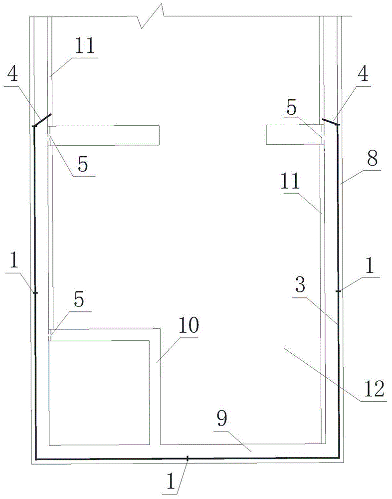
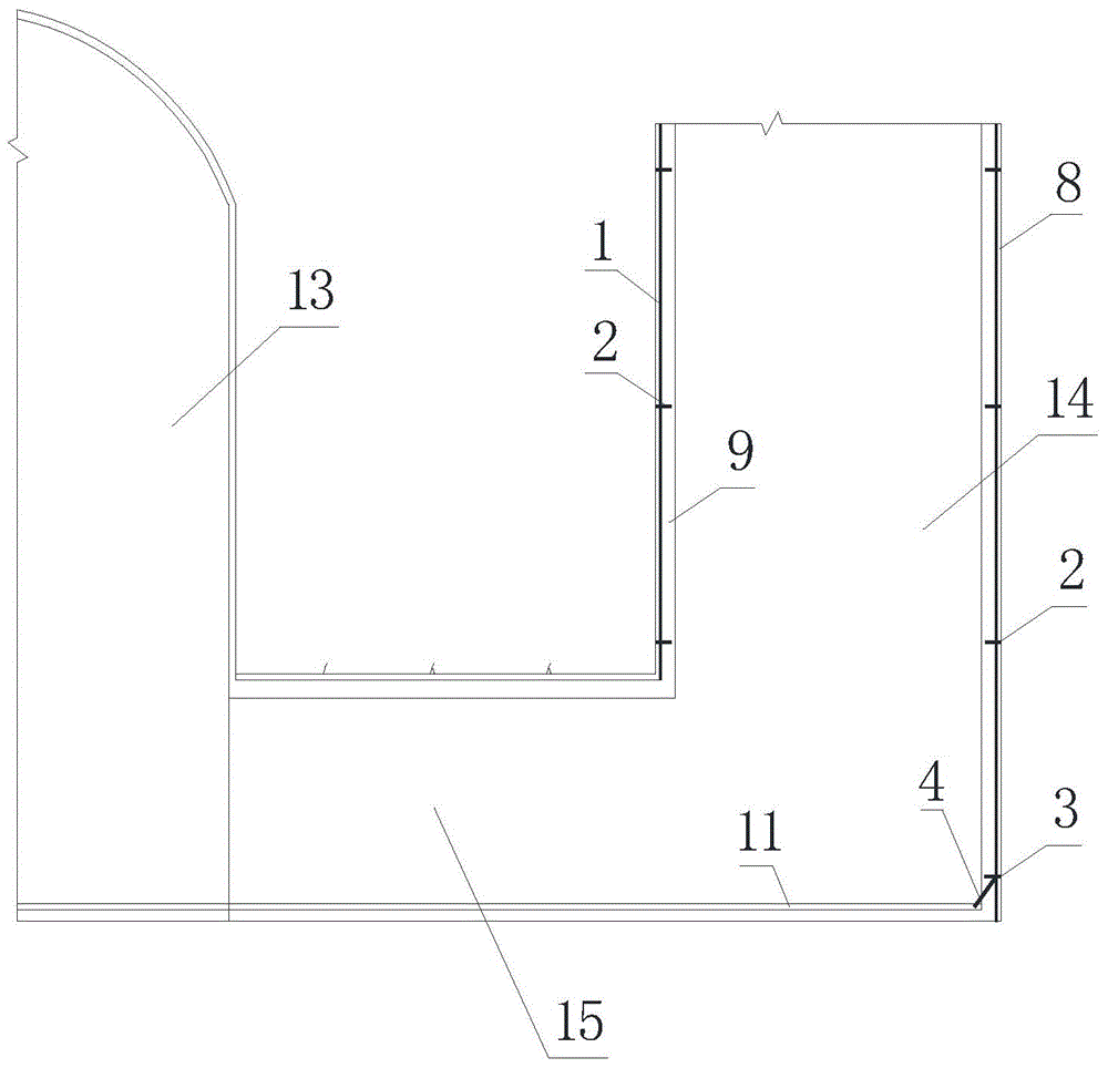
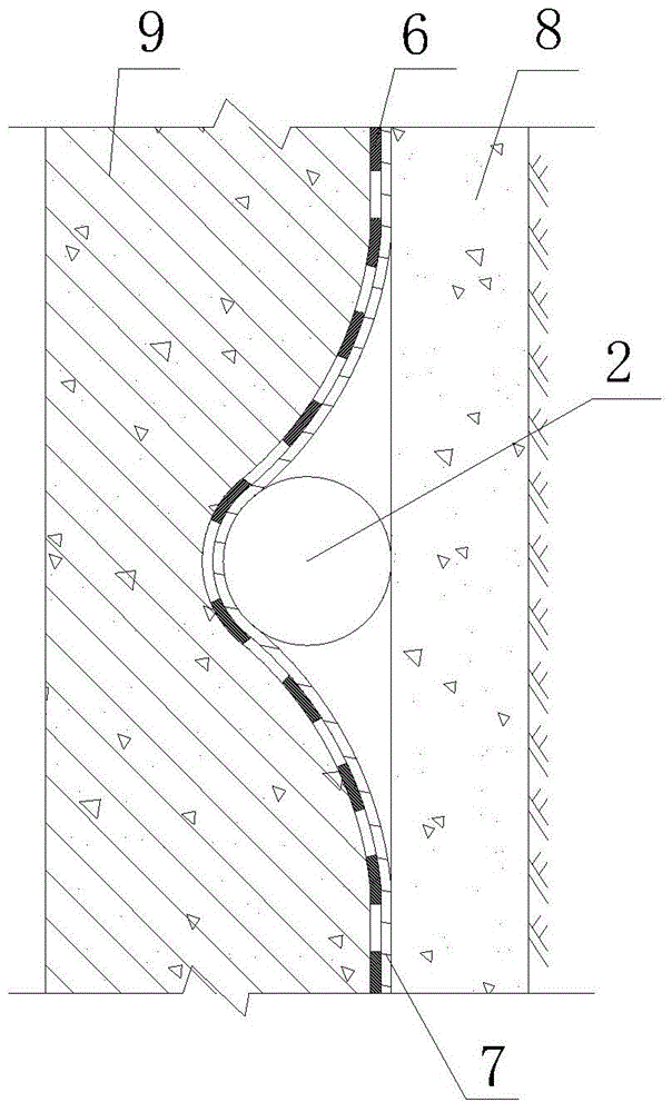
[0030] Such as Figure 1 to Figure 4 As shown, a vertical shaft waterproof and drainage structure of an underground factory building according to the present invention includes a main variable hole 13 connected to an outgoing line corridor 15 and an outgoing line shaft 14. The outlet shaft shaft consists of the first-stage shotcrete 8 and the second-stage lining concrete 9. A waterproof and drainage layer is arranged between the first-stage shotcrete 8 and the second-stage lining concrete 9. The waterproof and drainage The layer includes permeable pipes, a buffer layer 7 and a waterproof board 6 arranged in the shotcrete 8 of the first stage, and a concrete elevator shaft shaft 10 is also arranged in the vertical shaft of the underground workshop. In this technical scheme, after the ex...


PUM

PropertyMeasurementUnit
Thicknessaaaaaaaaaa
Diameteraaaaaaaaaa
Diameteraaaaaaaaaa

Abstract

The invention discloses a waterproof and drainage structure of a vertical shaft in an underground workhouse and a construction method for the waterproof and drainage structure. The waterproof and drainage structure of the vertical shaft comprises a main transformed cavern and a wire outlet vertical shaft which are connected by a wire outlet gallery, wherein the wire outlet vertical shaft consists of a vertical shaft base plate and a pitshaft of the wire outlet vertical shaft; the pitshaft of the wire outlet vertical shaft is connected with the periphery of the vertical shaft base plate and comprises first-phase pneumatically placed concrete and second-phase lining concrete; a waterproof and drainage layer is arranged between the first-phase shooting concrete and the second-phase lining concrete and comprises a pervious pipe, a buffer layer and a waterproof plate. The construction method comprises the following steps: digging and supporting the vertical shaft; laying the waterproof and drainage layer; casting the second-phase lining waterproof concrete. According to the waterproof and drainage structure and the construction method thereof disclosed by the invention, the diversion and drainage and the collection of palisades leaked water can be effectively realized, the cracking of secondary lining concrete is reduced, and a good waterproof and impervious effect is realized. In addition, by the adoption of the structural form, system draining holes can be reduced, and random draining holes are formed in places where the leakage is serious. The waterproof and drainage structure has the advantages of safety, environment friendliness, convenience for construction, high comprehensive benefit and the like.

Description

technical field [0001] The invention belongs to the technical field of water conservancy and hydropower, and in particular relates to an underground powerhouse shaft waterproof and drainage structure and a construction method thereof. Background technique [0002] At present, most underground powerhouse shafts have water leakage problems after excavation of the rock wall. If drainage is not carried out, the shaft lining will bear a lot of groundwater pressure, which will lead to thickening of the shaft concrete lining and large reinforcement. In addition, during the hardening process of the shaft lining concrete, there are temperature stress and shrinkage stress inside. The existence of these stresses will cause the concrete to deform, and the surface of the shotcrete is rough and uneven, which will inevitably have a considerable binding force on the lining concrete, preventing Its deformation, so just produced the tensile stress. When the tensile stress is greater than the...

Claims


Application Information

Patent Timeline
IPC IPC(8): E02D19/20E02D29/045
Inventor 周小乾刘恩举宁华晚宋静曾树元
Owner CHINA POWER CONSRTUCTION GRP GUIYANG SURVEY & DESIGN INST CO LTD
Why Eureka
Try Eureka