Laser image detection device and detection method for air preheater rotor deformation

An air preheater, image detection technology, applied in measurement devices, optical devices, instruments, etc., can solve problems affecting air leakage control effect, boiler maintenance and replacement, measurement result drift, etc., to improve effective running time and reliability. performance, easy installation and maintenance, and large measurement range

Active Publication Date: 2017-04-12
赵佑民
View PDF7 Cites 0 Cited by
  • Summary
  • Abstract
  • Description
  • Claims
  • Application Information

AI Technical Summary

Problems solved by technology

This working method leads to the installation structure of the eddy current probe in the furnace requiring mechanical moving parts, which is troublesome to install and use
[0014] 2. The corrosive substances inside the preheater will corrode the eddy current measurement coil and connecting wires, and the dust accumulation will cause changes in electrical parameters. These factors will cause the measurement results to drift and seriously affect the air leakage control effect
When the corrosion is severe, it will directly damage the measuring device and make the system completely inoperable
Therefore, the reliability of this detection method is relatively poor
[0015] 3. Since some easily damaged electronic components are installed in the furnace, once they are damaged, they cannot be repaired and replaced during the operation of the boiler, resulting in the air leakage of the preheater being unable to be effectively controlled for a long time, resulting in a significant decline in the comprehensive air leakage control effect of the preheater

Method used


Image

  • Laser image detection device and detection method for air preheater rotor deformation
  • Laser image detection device and detection method for air preheater rotor deformation
  • Laser image detection device and detection method for air preheater rotor deformation

Examples


Embodiment 1

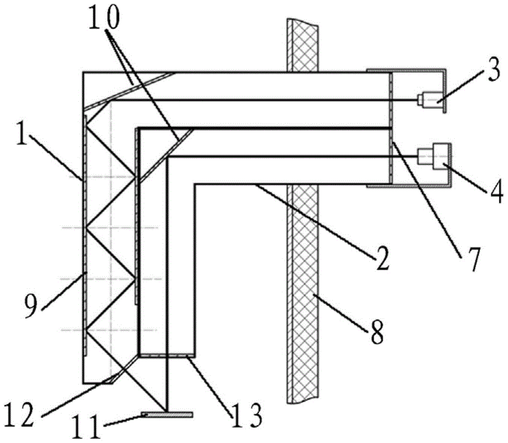
[0052] An embodiment of the present invention provides a laser image detection device for the deformation of the air preheater rotor, such as figure 1 As shown, the device includes: a first L-shaped channel 1, a second L-shaped channel 2, a laser emitter 3, and an image collector 4, the first L-shaped channel 1 is superimposed on the second L-shaped channel 2, And both are arranged horizontally, the inner wall of the vertical part of the first L-shaped channel 1 is relatively provided with a mirror 9, and the corners of the first L-shaped channel 1 and the second L-shaped channel 2 are provided with glass mirrors 10, The outlet of the first L-shaped passage 1 is provided with a first inner sealing glass 12 at an angle to the horizontal direction, and the entrance of the second L-shaped passage 2 is horizontally provided with a second inner sealing glass 13; An L-shaped channel 1 and a second L-shaped channel 2 are arranged above the rotor of the air preheater.

[0053] One en...

Embodiment 2

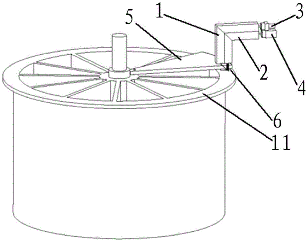
[0055] An embodiment of the present invention provides a laser image detection device for the deformation of the air preheater rotor, such as figure 1 , 2 As shown, the device includes: a first L-shaped channel 1, a second L-shaped channel 2, a laser emitter 3, and an image collector 4, the first L-shaped channel 1 is superimposed on the second L-shaped channel 2, And both are arranged horizontally, the inner wall of the vertical part of the first L-shaped channel 1 is relatively provided with a mirror 9, and the corners of the first L-shaped channel 1 and the second L-shaped channel 2 are provided with glass mirrors 10, The outlet of the first L-shaped passage 1 is provided with a first inner sealing glass 12 at an angle to the horizontal direction, and the entrance of the second L-shaped passage 2 is provided with a second inner sealing glass 13 horizontally; air preheating The fan-shaped plate 5 above the measuring reference plane 11 of the rotor rotor is provided with a p...

Embodiment 3

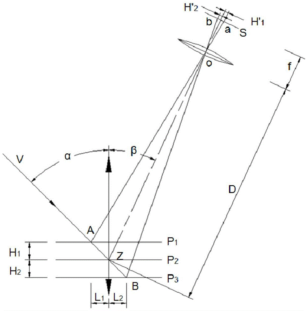
[0079] The embodiment of the present invention provides a laser image detection method for the deformation of the rotor of an air preheater. The method is as follows: the point-shaped laser beam emitted by the laser emitter 3 passes through the mirror surface at the inner corner of the first L-shaped channel 1 and the The specular reflection on the inner wall of the vertical part of the first L-shaped channel 1 is relatively arranged, so that the point-like laser beam is projected at an angle on the measurement reference plane 11 of the rotor of the air preheater to present a spot image, and the image collector 4 passes through the second L The specular reflection at the inner corner of the type channel 2 collects the spot images of the measurement reference plane 11 of the air preheater rotor at different positions, and obtains the absolute change of the air preheater rotor according to the spot images.


PUM


Abstract

The invention discloses a laser image detection device of air pre-heater rotor deformation. The detection device comprises a laser emitter, an image acquirer and two light path channels, wherein the laser emitter is used for emitting a laser beam, one path of the light path channel is used for projecting the laser beam emitted by the laser emitter to the measurement base level of an air pre-heater rotor, and representing light spot positions; the other light path channel is used for transmitting the light spots of the laser beam, represented on the measurement base level of the air pre-heater rotor, to the image acquirer; the image acquirer is used for acquiring the light spot positions on the measurement base level and acquiring the variation of the light spot positions according to the different light spot positions, and outputting rotor deformation information after mathematical transformation of the deformation of the light spot positions is performed. The invention further discloses a laser image detection method of the air pre-heater rotor deformation. Through the adoption of the device and the method disclosed by the invention, measurement information is provided for the closed-loop control of a sealing clearance.

Description

technical field [0001] The invention belongs to the technical field of measuring the deformation of an internal rotor of a rotary air preheater, and in particular relates to a laser image detection device and a detection method for the deformation of an air preheater rotor. Background technique [0002] "Rotary air preheater", also known as "Junker type air preheater", hereinafter referred to as "air preheater", is one of the main components of large industrial boilers, and is an important energy-saving equipment for boilers. It is a heat exchanger in principle, and its main function is to use the waste flue gas discharged from boiler combustion to preheat the combustion-supporting air that is about to enter the boiler combustion, thereby improving the thermal efficiency of the boiler. [0003] The main structure of the air preheater is a huge cylindrical rotor, which is divided into dozens of fan-shaped cylinders connected up and down by multiple sealed partitions along the...

Claims


Application Information

Patent Timeline
Patent Type & Authority Patents(China)
IPC IPC(8): G01B11/16
Inventor 赵佑民
Owner 赵佑民
Why Eureka
Try Eureka