Time-grating angular displacement sensor based on quadrature modulation of light intensity

An angular displacement sensor and quadrature modulation technology, applied in the field of sensors, can solve the problems of increasing the difficulty of processing technology, difficult circuit control, complex processing circuit, etc. Effect

Active Publication Date: 2015-05-27
CHONGQING UNIV OF TECH
View PDF9 Cites 8 Cited by
  • Summary
  • Abstract
  • Description
  • Claims
  • Application Information

AI Technical Summary

Problems solved by technology

If the structure is simply changed to measure the angular displacement, there will be the following problems: (1) the multi-channel photoelectric receiving circuit makes the processing circuit complex and the circuit control is difficult; (2) both the fixed plate and the moving plate are double-row grids, The installation is difficult, and when measuring the angular displacement, the grid surfaces with different radii are required to ensure the same area, which will increase the difficulty of the processing technology and increase the cost

Method used


Image

  • Time-grating angular displacement sensor based on quadrature modulation of light intensity
  • Time-grating angular displacement sensor based on quadrature modulation of light intensity
  • Time-grating angular displacement sensor based on quadrature modulation of light intensity

Examples


Embodiment 1

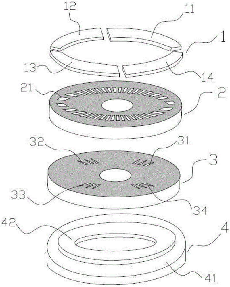
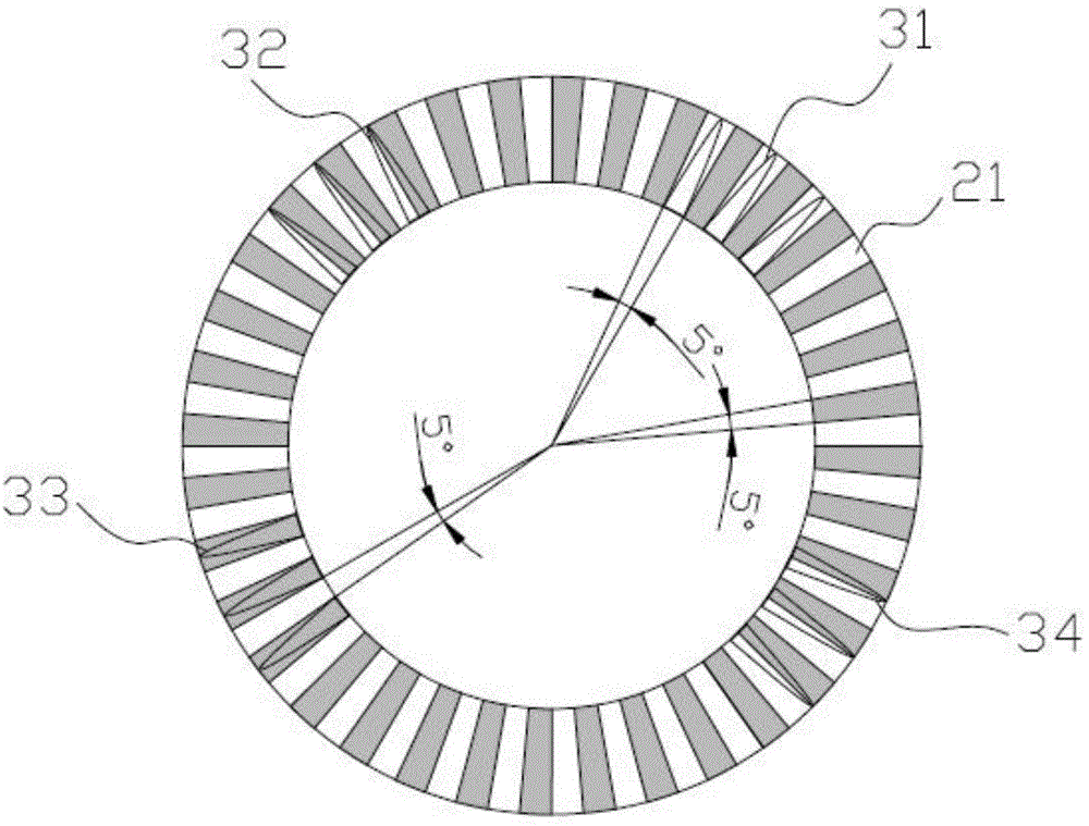
[0026] Embodiment 1: as Figure 1 to Figure 5 The shown time grating angular displacement sensor based on light intensity quadrature modulation includes a light emitting element 1, a moving plate base 2, a fixed plate base 3 and a photodetector 4, and the light emitting element 1, the fixed plate base 3 and the photodetector 4 are all Relatively fixed, only the moving plate base body 2 can rotate.

[0027] The light-emitting element 1 is installed on the top of the moving plate base 2, and the light-emitting element 1 is spaced successively along the circumferential direction by the first light source body 11, the second light source body 12, the third light source body 13 and the fourth light source body 14 which are equal in size and do not interfere with each other. Arrangement structure, the first light source body 11, the second light source body 12, the third light source body 13 and the fourth light source body 14 all adopt fan-shaped light emitting diode arrays, and th...

Embodiment 2

[0040] Embodiment 2: as Figure 6 to Figure 8 The shown time grating angular displacement sensor based on light intensity quadrature modulation, most of its structure and measurement principle are the same as those in Embodiment 1, the difference is: the first light source body 11, the second light source body 12, the third light source body 13 and the fourth light source body 14 all adopt fan-shaped semiconductor surface light sources, and the photoelectric measuring head 42 is composed of fan-shaped first photosensitive array 421, second photosensitive array 422, third photosensitive array 423, fourth The photosensitive array 424 is sequentially arranged at intervals along the circumferential direction, and receives the first set of fixed plate light-transmitting surfaces 31, the second set of fixed plate light-transmitting surfaces 32, the third set of fixed plate light-transmitting surfaces 33, and the fourth set of fixed plate light-transmitting surfaces respectively. The...


PUM


Abstract

The invention discloses a time-grating angular displacement sensor based on quadrature modulation of light intensity. The time-grating angular displacement sensor comprises a light-emitting element, a movable disc matrix, a fixed disc matrix and a photoelectric detector, wherein the light-emitting element is formed by circumferentially arranging a first power source body, a second power source body, a third power source body and a fourth power source body which have the same size and are driven by sine excitation signals with the same frequency and the same amplitude and the phase difference of 90 degrees respectively; a circle of fan ring-shaped movable disc light transmission surface is arranged on the movable disc matrix; a first group, a second group, a third group and a fourth group of fixed disc light transmission surfaces are circumferentially arranged on the fixed disc matrix; the spatial phases of the fixed disc light transmission surfaces correspond to the illumination regions of the four power source bodies; all groups of the fixed disc light transmission surfaces should meet a certain corresponding relationship with the movable disc light transmission surface; the photoelectric detector comprises a detection head matrix, and photoelectric detection heads which are fixed on the detection head matrix and can receive light fluxes of the four groups of the fixed disc light transmission surfaces at the same time. The time-grating angular displacement sensor can precisely measure an angular displacement, and can reduce the circuit control difficulty, the mounting difficulty and the machining process difficulty.

Description

technical field [0001] The invention relates to a sensor, in particular to a time grating angular displacement sensor based on light intensity quadrature modulation. Background technique [0002] The photoelectric encoder is mainly used in the field of precision angular displacement measurement. The photoelectric encoder is a sensor that converts the mechanical and geometric displacement input to the shaft into pulse or digital quantity through photoelectric conversion. The photoelectric encoder is composed of a grating disc and a photoelectric detection device. The grating disc is regularly engraved with light-transmitting and opaque lines. Light-emitting elements and photosensitive elements are placed on both sides of the grating disc. The grating disc rotates at the same speed as the motor. A number of pulse signals are output through detection by the light-emitting diode detection device. Its measurement accuracy and resolution depend on the number of lines on the circu...

Claims


Application Information

Patent Timeline
Patent Type & Authority Applications(China)
IPC IPC(8): G01B11/26
Inventor 付敏刘小康彭东林朱革夏豪杰
Owner CHONGQING UNIV OF TECH
Why Eureka
Try Eureka