High-efficiency electric ESR (Electroslag Refining/Remelting) ingot casting device

An electroslag ingot and high-efficiency technology, applied in the field of electroslag remelting equipment, can solve the problems of ingot shape limitation, low work efficiency, complex structure, etc., and achieve the effects of low cost, high work efficiency and wide application range

Inactive Publication Date: 2015-06-03
JIANGSU MARITIME INST
View PDF0 Cites 0 Cited by
  • Summary
  • Abstract
  • Description
  • Claims
  • Application Information

AI Technical Summary

Problems solved by technology

It uses the resistance heat generated by the current passing through the liquid slag to continuously melt the metal electrode, the molten metal gathers into droplets, passes through the slag layer and drops into the molten metal pool, and solidifies into a casting in a special-shaped water-cooled mold at the same time; Most of the large-scale electroslag remelting furnaces in the domestic electroslag metallurgy industry have complex structures and high costs, and the shape of the formed steel ingot is limited, and the degree of freedom is small; and the output current of the transformer is industrial frequency, the power factor, and the power consumption are large. , high-power transformers that use single-phase power in and out generally need to add dynamic compensation devices to reduce the impact on the power grid, but the investment is large and the work efficiency is low. Therefore, a new technical solution is urgently needed to solve the above-mentioned technical problems. question

Method used


Image

  • High-efficiency electric ESR (Electroslag Refining/Remelting) ingot casting device

Examples


Embodiment 1

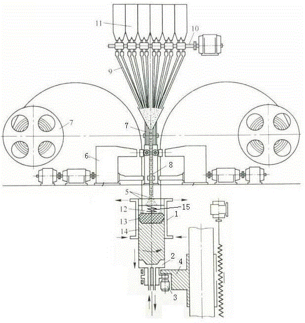
[0015] Example 1: See figure 1 , Efficient electric slag ingot melting casting device, the melting casting device includes feeding devices, feeding devices, control devices, reaction devices, and bottom water tank components.Between the bottom water tank parts, the molten casting device also includes a water -cooled crystallizer 1, which is set on the outside of the reaction device.Inside.The overall structure of the invention is clever, the structure is compact, and the practicality is strong; the technical solution is set in the mixing device to make the metal liquid in the metal pool more fully stirred, which is convenient for forming various shapes of steel ingots.higher efficiency.

Embodiment 2

[0016] Example 2: See figure 1 As a improvement of the present invention, the input device includes material grooves 11, raw material quantitative 10, which is set below the groove.The remaining structures and advantages are exactly the same as Example 1.

Embodiment 3

[0017] Example 3: See figure 1 As a improvement of the present invention, the feeding device includes the guide pipe 8 and the feed pipe 9. The feed pipe is set up above the guide pipe, and the feed pipe is set to a cone.The remaining structures and advantages are exactly the same as Example 1.


PUM


Abstract

The invention relates to a high-efficiency electric ESR (Electroslag Refining / Remelting) ingot casting device. The casting device comprises a charging device, a feeding device, a control device, a reaction device and a bottom water tank component, wherein the feeding device is arranged above the feeding device; the reaction device is arranged between the control device and the bottom water tank component; the casting device also comprises a water-cooling crystallizer which is arranged on the outer side of the reaction device; the casting device also comprises a stirring device which is arranged in the water-cooling crystallizer. The high-efficiency electric ESR ingot casting device has the advantages that steel ingots of different shapes, such as roundness, square, rectangle, cross-section shape with large proportion of wide and narrow surfaces and the like can be formed by the high-efficiency electric ESR ingot casting device adopting the technical scheme, so that the freedom degree is relatively large and the application is relatively wide. The stirring device is arranged in the technical scheme, so that molten metal in a metal tank is stirred more sufficiently so as to facilitate to form various shapes of steel ingots, and the freedom degree of design is larger and the working efficiency is higher.

Description

Technical field [0001] The present invention involves a melting casting device, especially a high -efficiency electric slag ingot melting device, which belongs to the technology field of electric slag heavy melting equipment. Background technique [0002] Electric slag melting casting is a process that makes metal refining and casting into one at one time, producing high -quality alloy castings.It is a technology that uses the resistance heat generated by the current through the current through the current through the fluid residue, and the metal electrodes are constantly melted., Most of the large -scale electric slag melting furnaces in the domestic electric slag metallurgical industry are complicated, the cost is high, and the shape of the steel ingot is limited, and the degree of freedom is small., To use single -phase entry and exit high -power transformers generally add dynamic compensation devices to achieve the effect of reducing the impact on the grid, but the investment...

Claims


Application Information

Patent Timeline
Patent Type & Authority Applications(China)
IPC IPC(8): B22D23/10
CPCB22D23/10
Inventor 杨书杰李秋波王刚华孙厚法丁龙祥
Owner JIANGSU MARITIME INST
Why Eureka
Try Eureka