Electrolytic chlorine dioxide generator and electrolytic cell

A chlorine dioxide and electrolytic cell technology, applied in the electrolysis process, electrolysis components, cells, etc., can solve the problems of low degree of automation control, low purity of chlorine dioxide, and affecting equipment performance, etc., to achieve high purity of chlorine dioxide, Simple structure and long service life

Active Publication Date: 2015-06-03
四川普尔环保有限公司
View PDF8 Cites 2 Cited by
  • Summary
  • Abstract
  • Description
  • Claims
  • Application Information

AI Technical Summary

Problems solved by technology

[0004] First of all, the electrolysis efficiency of this type of electrolytic cell design has certain limitations, and the effect is not ideal; secondly, the existing technology usually uses industrial salt as the electrolysis raw material, and the disinfection components generated in the anode chamber include chlorine dioxide, chlorine gas, ozone and peroxide. Hydrogen oxide, etc., so the purity of chlorine dioxide is not high; third, it adopts a box-like appearance, an open control system, and the cathode chamber is not completely isolated from the air. The chlorine dioxide gas continuously produced in the anode chamber is easy to overflow and pollute the environment. At the same time, the structure is complex and the degree of automation control is relatively low; Chlorine effect; Fifth, the middle diaphragm is prone to high damage rate and short service life due to the pressure difference between the cathode chamber and the anode chamber

Method used


Image

  • Electrolytic chlorine dioxide generator and electrolytic cell
  • Electrolytic chlorine dioxide generator and electrolytic cell
  • Electrolytic chlorine dioxide generator and electrolytic cell

Examples


Embodiment Construction

[0051] The present invention will be further described in detail below in conjunction with the accompanying drawings, so that those skilled in the art can implement it with reference to the description.

[0052]It should be understood that terms such as "having", "comprising" and "including" used herein do not exclude the presence or addition of one or more other elements or combinations thereof.

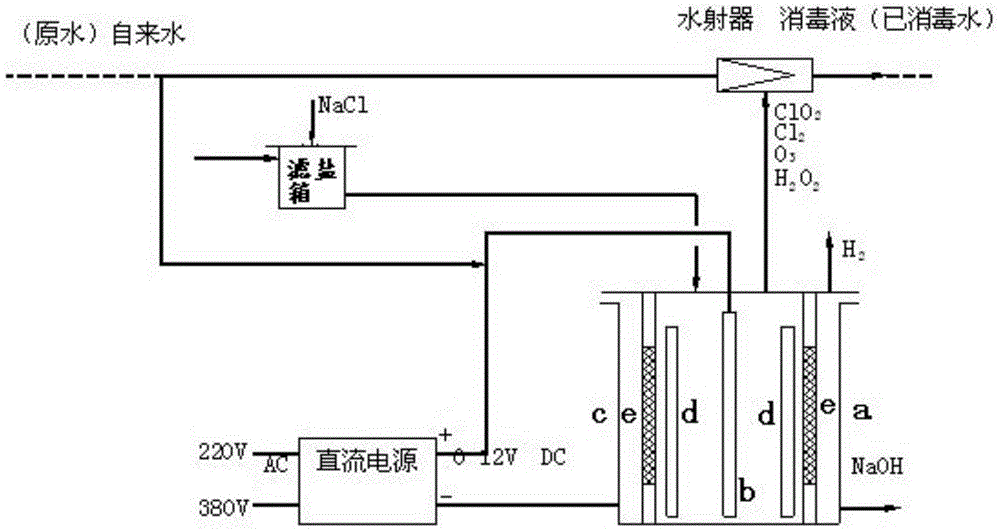
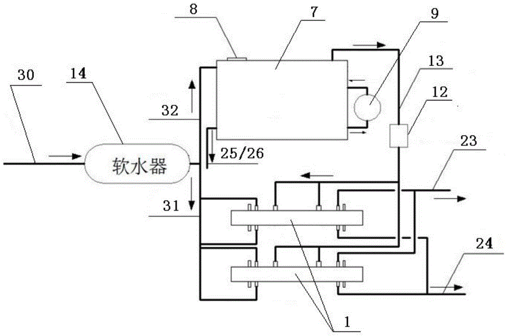
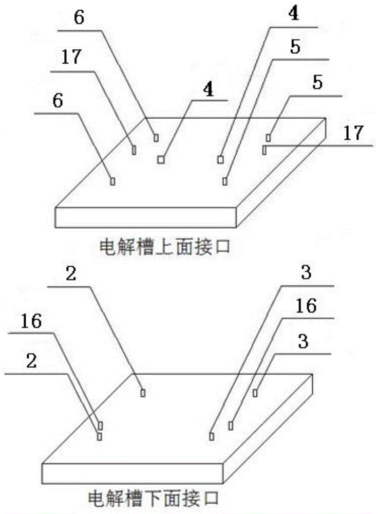
[0053] combine Figure 2-6 , the present invention at first provides an electrolytic cell for an electrolytic chlorine dioxide generator, which comprises:

[0054] A hollow electrolyzer body 1;

[0055] An intermediate diaphragm (not shown), which is arranged inside the electrolyzer body and separates the inside of the electrolyzer body into two chambers;

[0056] Cathode and anode plates (not shown), which are respectively arranged on both sides of the intermediate diaphragm to form a micro-pole pitch, and simultaneously form the two chambers respectively a cathode and an anode c...


PUM


Abstract

The invention discloses an electrolytic chlorine dioxide generator and an electrolytic cell. The electrolytic cell comprises a hollow electrolytic cell body, an intermediate diaphragm, a positive plate and a negative plate, wherein the intermediate diaphragm is arranged in the electrolytic cell body, and divides the interior of the electrolytic cell body into two chambers; the positive and negative plates are arranged on the two sides of the intermediate diaphragm respectively, and form micro polar distances; in addition, the two chambers form a positive chamber and a negative chamber respectively; the positive chamber and the negative chamber are a micro-volume positive chamber and a micro-volume negative chamber. The chlorine dioxide generator has a cabinet structure with the electrolytic cell, and is provided with a salt dissolution system, a salting system, a power system, a water softening system and a control system. According to the electrolytic cell, a neutral electrode in the conventional electrolytic method is eliminated, the positive and negative plates and the intermediate diaphragm form the micro polar distances, and in addition, a micro-volume design is adopted, so that the electrolytic efficiency of the equipment can be maximally improved when the electrolytic cell is used for the chlorine dioxide generator, the stability of the intermediate diaphragm can be improved, and the service life of the equipment can be prolonged.

Description

technical field [0001] The invention relates to a disinfectant generating device. More specifically, the present invention relates to an electrolytic chlorine dioxide disinfectant generator and electrolytic cell for producing disinfectant. Background technique [0002] The DFC series electrolytic chlorine dioxide generator was produced by introducing advanced production technology from the United States in the 1990s. After localization and serialization, it was produced through technical improvement and upgrading on the basis of the original series of products. It has now been upgraded to the fifth generation of products. Not only in The stability of the equipment has been greatly improved, and a huge breakthrough has been made in terms of service life and safety performance. The current DFC series equipment has realized fully automatic control operation. It does not need human operation on duty and adding salt (raw material) every day. It can automatically operate accordin...

Claims


Application Information

Patent Timeline
IPC IPC(8): C25B9/00C25B15/00C25B1/46
Inventor 张学武
Owner 四川普尔环保有限公司
Why Eureka
Try Eureka