Oil well drilling damping device

A shock absorber and oil well technology, applied in the direction of shock absorber, spring/shock absorber, shock absorber, etc., can solve the problems of increasing the quality of drilling tools, and achieve the goals of improving service life, uniform magnetic field distribution and prolonging service life Effect

Active Publication Date: 2015-06-03
北方石油作业公司
View PDF8 Cites 4 Cited by
  • Summary
  • Abstract
  • Description
  • Claims
  • Application Information

AI Technical Summary

Problems solved by technology

These adjustable shock absorbers change the flow area by adjusting the opening size of the orifice, so as to adjust the damping coefficient, and the output damping force changes with the stroke of the piston on the shock absorber; but when dealing with a large impact It must be realized by reducing the throttle and increasing the stroke of the piston, resulting in an increase in the quality of the drilling tool during drilling

Method used


Image

  • Oil well drilling damping device

Examples


Embodiment

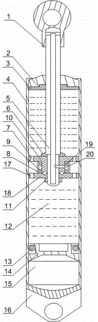
[0022] Such as figure 1As shown, this embodiment includes a working cylinder 4 with both ends sealed and a piston rod 5 that penetrates through the end cover 2 of the working cylinder 4 and its end is placed in the working cylinder 4. A longitudinal The cross-section is a "T" type piston 10, two semicircular baffles 18 are hinged at the end of the vertical part of the piston 10, and a gasket 6 is installed on the upper end of the piston 10, and a ring for fixing the piston 10 and The nut 11 of the baffle plate 18 has a plurality of upper discharge holes 7 on the horizontal part of the piston 10, and has a plurality of lower discharge holes 17 corresponding to the upper discharge holes 7 on the two baffle plates 18. The aperture of the upper discharge hole 7 increases from the middle to both ends. A coil group is arranged in the middle of the piston 10, and an isolation ring 8 is arranged on the outer wall of the coil group. The inside of the piston rod 5 is hollow, and the co...


PUM


Abstract

The invention discloses an oil well drilling damping device which comprises a work cylinder and a piston rod. The tail end of the piston rod is in threaded connection with a piston, the longitudinal section of the piston is in a T shape, two semicircular blocking plates are hinged to the tail end of the vertical portion of the piston, a plurality of upper leakage flow holes are formed in the horizontal portion of the piston, a plurality of lower leakage flow holes corresponding to the upper leakage flow holes are formed in the two blocking plates, the hole diameters of the upper leakage flow holes gradually increase from middle to two ends, and a coil assembly is arranged in the middle of the piston. When the oil well drilling damping device is used, the hole diameters of the leakage flow holes gradually increase from middle to two ends, a middle contraction opening of the leakage flow holes is achieved, and the grasp force, at the upper end and the lower end of the middle contraction opening, of magnetorheological fluid to the piston is enhanced. Meanwhile, the piston is started up and shut down in the work cylinder through quick conversion of external voltage. Due to the fact that no throttle valve with the variable throttle size is arranged in the oil well drilling damping device, the mechanical abrasion resistance of the oil well drilling damping device is greatly improved, and the service life of the oil well drilling damping device is prolonged.

Description

technical field [0001] The invention relates to a shock absorbing device, in particular to a shock absorbing device used for oil well drilling. Background technique [0002] In oil drilling, the drilling tool is driven to break the rock, drill into the ground, and drill a wellbore with a specified depth for the oil or gas extraction machine to obtain oil or natural gas. a regular oil drilling rig It is mainly composed of power machine, transmission machine, working machine and auxiliary equipment. The drilling tool is equipped with a hoisting system for lifting and lowering the drilling tool, running the casing, controlling the drilling pressure, and feeding the drilling tool; the lifting system includes a winch, auxiliary brake, crown block, traveling block, hook, wire rope and lifting ring , Elevators, hanging clamps, slips and other tools. When hoisting, the winch drum winds the steel wire rope, the crown block and traveling block constitute the auxiliary pulley block,...

Claims


Application Information

Patent Timeline
Patent Type & Authority Applications(China)
IPC IPC(8): F16F9/06F16F9/342F16F9/50F16F9/53
CPCF16F9/061F16F9/3405F16F9/36F16F9/368F16F9/50F16F9/535
Inventor 王贺华刘榧周长江张博米中荣康博邓勇杨鸿杨滔蒋利平付辉符奇何巍袁浩马成张艺久黄海平臧克一李鑫刘家材桂碧雯黄凯孙照磊
Owner 北方石油作业公司
Why Eureka
Try Eureka