
Three-dimensional elastic support

An elastic bearing, three-dimensional technology, applied in the direction of supporting machines, pipeline supports, machines/supports, etc., can solve problems such as large pipeline stress, damage to equipment and facilities, material waste, etc., to absorb or buffer vibration, reduce vibration, and apply Sexually wide effect

Active Publication Date: 2015-06-03
BC P INC CHINA NAT PETROLEUM CORP +1
View PDF6 Cites 30 Cited by
  • Summary
  • Abstract
  • Description
  • Claims
  • Application Information

AI Technical Summary

Problems solved by technology

[0002] At present, for some equipment and facilities with special structures and complicated operating conditions, rigid support will cause excessive local stress in the structure, the stress state does not meet the requirements of the code, and it is easy to cause damage to the equipment and facilities
For example, the gas phase pipeline connected to the scraper condenser in the polyester plant has a large size, high temperature, and high rigidity of the system, which will generate large pipeline stress when heated; the vertical and horizontal dimensions of the scraper condenser itself are large , has a certain amount of expansion; the self-weight of the equipment itself and the gravity of the material, as well as the vibration caused by the rotating parts; due to these complex additional loads, thermal expansion, vibration and other factors, the traditional rigid support cannot meet the normal use of the equipment
In order to solve such problems, equipment designers usually adopt two methods: increasing the size of components or increasing the strength level of structural materials. On the one hand, it causes waste of materials, and on the other hand, it cannot fundamentally solve the problem

Method used


Image

  • Three-dimensional elastic support
  • Three-dimensional elastic support
  • Three-dimensional elastic support

Examples


Embodiment Construction

[0020] Specific embodiments of the present invention will be described in detail below in conjunction with the accompanying drawings.

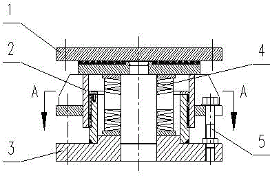
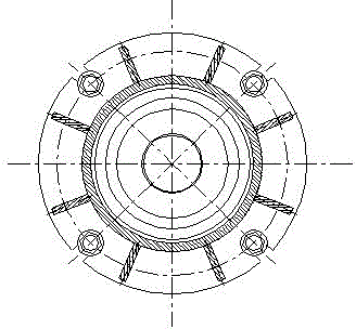
[0021] Referring to Figure 1-4, according to the specific conditions of different types of equipment and facilities, a single equipment or facility can generally be used in combination with a single, two, four or six three-dimensional elastic bearings, and a steel structure frame can also be used if necessary As a basic frame, the equipment is placed on the basic frame as a whole, and the elastic support is placed under the basic frame. For example, the use of a single three-dimensional elastic support, a special pipe support that can be used as a single fulcrum support, etc.

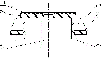
[0022] The sliding plate 1 of the three-dimensional elastic support is fixed to the bottom (or base frame) of the supported equipment with bolts or welding, and the equipment slides between the sliding plate 1 and the PTFE backing plate 2-1 of the top seat 2 to achieve ...


PUM


Abstract

The invention relates to a three-dimensional elastic support. The three-dimensional elastic support comprises a sliding plate, a top seat, a pedestal and a disk spring component, wherein the lower surface of the sliding plate is a smooth plane; the main body of the top seat is inverted cup-shaped; the sliding plate is positioned on a top plate of the top seat; the top plate is connected with a guide column which extends downwards; the main body of the pedestal is cup-shaped; an upper sleeve of the pedestal is cylindrical; the disk spring component sleeves the guide column, the upper end is supported against the top plate, and the lower end is supported against the bottom plate; an upper flange on the upper sleeve and a lower flange on the bottom plate are provided with threaded fastening members. The support has a simple, firm and durable structure and wide applicability; the requirement on free sliding in a three-dimensional space of a supported object can be met while complex change load is born; the supported object is also allowed to rotate around the normal of the supporting surface; the support is particularly suitable for supporting facilities and equipment under complex working conditions such as superimposed changeable load and multi-dimensional deformation.

Description

technical field [0001] The invention relates to a three-dimensional elastic bearing, which can be mainly used in the engineering fields of petrochemical industry, water conservancy and electric power, light industry, textile, road and bridge, etc., and is especially suitable for complex working conditions such as superimposed variable load and multi-dimensional deformation. Support for facilities and equipment. Background technique [0002] At present, for some equipment and facilities with special structures and complicated operating conditions, rigid support will cause excessive local stress in the structure, and the stress state does not meet the requirements of the specification and may easily cause damage to the equipment and facilities. For example, the gas phase pipeline connected to the scraper condenser in the polyester plant has a large size, high temperature, and high rigidity of the system, which will generate large pipeline stress when heated; the vertical and h...

Claims


Application Information

Patent Timeline
Patent Type & Authority Applications(China)
IPC IPC(8): F16M11/08F16F15/073F16L3/16E01D19/04
Inventor 许贤文殷昌创万网胜张锦徐科隋克鹏曾义
Owner BC P INC CHINA NAT PETROLEUM CORP
Learn More