Method and system for dynamically distributing resources in microcontroller unit MCU

A micro control unit and dynamic allocation technology, applied in the MCU field, can solve problems such as chip discarding, high SRAM, chip waste, etc., and achieve the effects of improving performance, effective utilization, and miniaturization

Inactive Publication Date: 2015-06-03
GIGADEVICE SEMICON (BEIJING) INC
View PDF7 Cites 17 Cited by
  • Summary
  • Abstract
  • Description
  • Claims
  • Application Information

AI Technical Summary

Problems solved by technology

[0003] MCU is a general-purpose chip. According to individual needs, an MCU chip will generally customize multiple product series (several or even dozens of product series). The size of the flash SRAM in the chip is determined according to the largest flash memory capacity. The individual requirements of different products have different requirements for flash memory capacity. However, in many customized products, it is not necessary to support the largest flash memory capacity, which will cause some flash SRAMs to be idle and wasteful.
Moreover, when there is idle and wasted flash SRAM, the chip area will be larger than the actual demand, which is not conducive to chip miniaturization
[0004] On the other hand, the flash memory capacity and memory capacity of each product are fixed, so there are often cases where some flash memory SRAM is idle and wasteful, while the memory capacity is not enough
[0005] In addition, the area of ​​the entire SRAM is relatively large, so the probability of SRAM defects in chip production is relatively high. The general processing method is to discard the chip, but in fact not all SRAM blocks are defective. In case only part of the SRAM block is defective
In this way, only a small piece of SRAM has a defect in the production process, which will cause the entire chip to be discarded, resulting in a huge waste of chips

Method used


Image

  • Method and system for dynamically distributing resources in microcontroller unit MCU
  • Method and system for dynamically distributing resources in microcontroller unit MCU
  • Method and system for dynamically distributing resources in microcontroller unit MCU

Examples


Embodiment 1

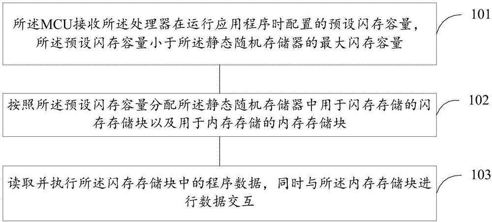
[0065] refer to figure 1 , which shows a flow chart of a method for dynamically allocating resources in a micro control unit MCU according to Embodiment 1 of the present invention, the MCU includes a processor and a SRAM, and the SRAM includes a plurality of storage blocks, the method Can include the following steps:

[0066] Step 101. The MCU receives a preset flash memory capacity configured by the processor when running an application program, and the preset flash memory capacity is smaller than the maximum flash memory capacity of the SRAM.

[0067] In the embodiment of the present invention, the MCU includes a processor (CPU) for processing application programs, and a static memory SRAM. The static memory includes a plurality of storage blocks, which can be used to store data in flash memory or internal memory. In the embodiment of the present invention, the application program can carry the preset flash memory capacity, and the user can configure and determine the flash...

Embodiment 2

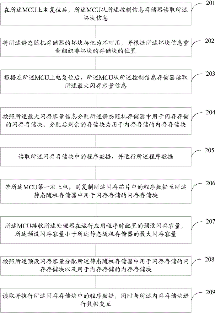
[0076] refer to figure 2 , shows a flowchart of a method for reading system configuration information of an MCU according to Embodiment 2 of the present invention.

[0077] In the embodiment of the present invention, the MCU includes a processor and a SRAM, and the SRAM includes a plurality of storage blocks.

[0078] The method may include the steps of:

[0079] Step 201. After the MCU is powered on and reset, the MCU reads the bad block information from the control information storage.

[0080] Step 202: Mark the bad block of the SRAM as unusable, and reorganize the location of the non-bad block storage blocks according to the bad block information.

[0081] Different from the previous embodiment, in this embodiment, the MCU further includes a control information storage, and the control information storage stores bad block information of the SRAM.

[0082] The control information memory adopts OTP (One Time Programmable, one-time programmable) storage method. Usually, a...

Embodiment 3

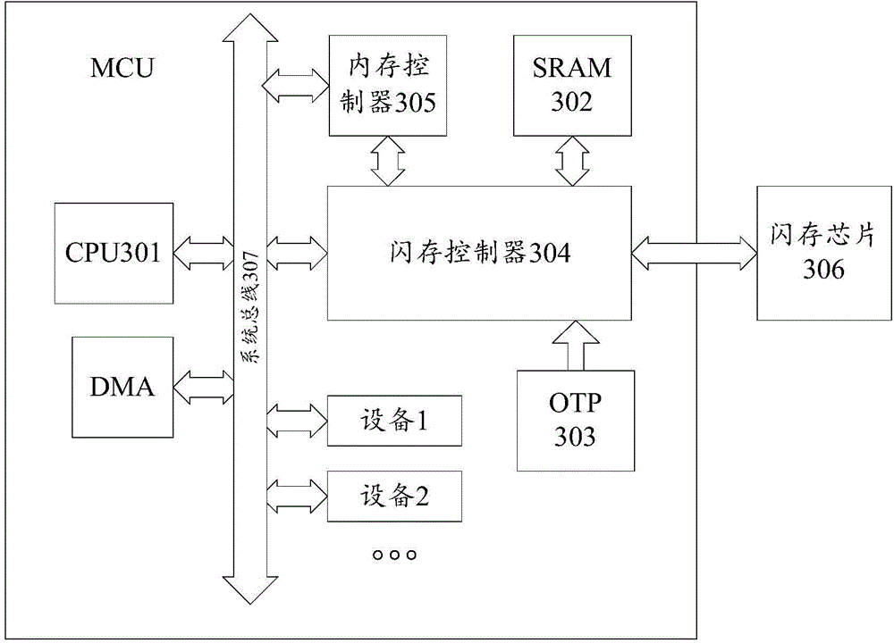
[0105] First, introduce the overall structure of the MCU in the embodiment of the present invention, as image 3 As shown, the MCU may include a CPU 301 , an SRAM 302 , an OTP 303 , a flash memory controller 304 , a memory controller 305 , a flash memory chip 306 and a system bus 307 . They are described as follows:

[0106] CPU301: CPU handles program data, and program data can be read from flash memory.

[0107] SRAM302: SRAM is a standard IP. In the present invention, the memory data and the data in the flash memory chip are stored, and the data will be lost after power off. The reading and writing speed is fast, and it can be read and written in real time.

[0108] OTP303: OTP is a storage type, which means one-time programmable. Usually, the product configuration information is programmed once during the product testing phase, and the data will not be lost when the power is turned off.

[0109] Flash memory controller 304: the function of the flash memory controller is ...


PUM


Abstract

The invention provides a method and a system for dynamically distributing resources in a microcontroller unit MCU. The MCU comprises a processor and a static random access memory, wherein the static random access memory comprises a plurality of memory blocks. The method comprises the following steps: the MCU receives a pre-set flash memory capacity which is configured by the processor when an application program is applied; the pre-set flash memory capacity is smaller than a maximum flash memory capacity of the static random access memory; a flash memory storage block for flash memory storage and an internal memory storage block for internal memory storage in the static random access memory are distributed according to the pre-set flash memory capacity; program data in the flash memory storage block is read and executed, and data interaction is carried out with the internal memory storage block. The method and the system can be suitable for requirements of different products, different customers and different application scenes, and a condition that the flash memory capacity is idle and wasted and the internal memory capacity is not enough is avoided.

Description

technical field [0001] Embodiments of the present invention relate to the technical field of MCUs, and in particular, relate to a method and system for reading system configuration information in an MCU. Background technique [0002] Micro Control Unit (MCU), also known as Single Chip Microcomputer (SCM) or single-chip microcomputer, refers to the computer's central processing unit (Central Processing Unit, CPU), static random access memory (Static Random Access Memory, SRAM), read-only memory (Read-Only Memory, ROM), timer counter and various I / O interfaces are integrated on a chip to form a chip-level computer. Do different combination control for different application occasions. The entire SRAM is divided into a memory SRAM and a flash SRAM, the memory SRAM temporarily stores memory data, and the flash SRAM temporarily stores flash memory chip data. [0003] MCU is a general-purpose chip. According to individual needs, an MCU chip will generally customize multiple produ...

Claims


Application Information

Patent Timeline
Patent Type & Authority Applications(China)
IPC IPC(8): G06F9/50G06F12/06
Inventor 王南飞李宝魁
Owner GIGADEVICE SEMICON (BEIJING) INC
Why Eureka
Try Eureka