Manufacturing method of chip type inductor

A manufacturing method and inductor technology, applied in the field of inductors, can solve the problems of costly procedures and working hours, and achieve the effects of high current resistance, avoiding leakage current phenomenon, and high heat resistance

Inactive Publication Date: 2015-06-03
KUNSHAN MAJI ELECTRONICS
View PDF8 Cites 0 Cited by
  • Summary
  • Abstract
  • Description
  • Claims
  • Application Information

AI Technical Summary

Problems solved by technology

Due to the large number of parts and components of this kind of ind

Method used


Image

  • Manufacturing method of chip type inductor
  • Manufacturing method of chip type inductor
  • Manufacturing method of chip type inductor

Examples


Embodiment Construction

[0049] Hereby relevant technical content and detailed description of the present invention, now coordinate drawing description as follows:

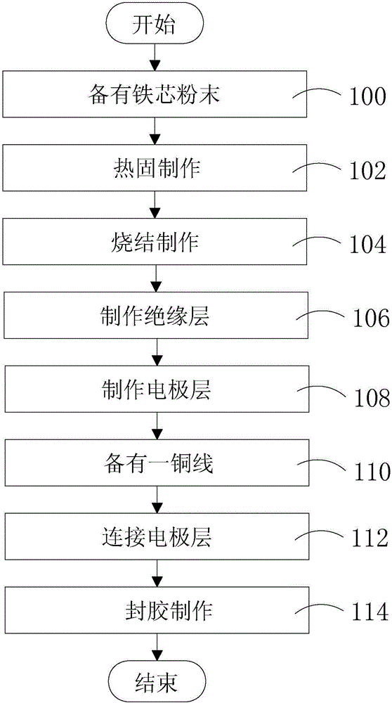
[0050] see Figure 1~Figure 7 , is a schematic diagram of the manufacturing process and structure of the chip inductor of the present invention. As shown in the figure: the manufacturing method of the chip inductor of the present invention, at first, as step 100, has iron core powder, and this iron core powder is the iron-nickel 50 powder of iron-silicon powder material (FeSi) or soft magnetic material ( FeNi50).

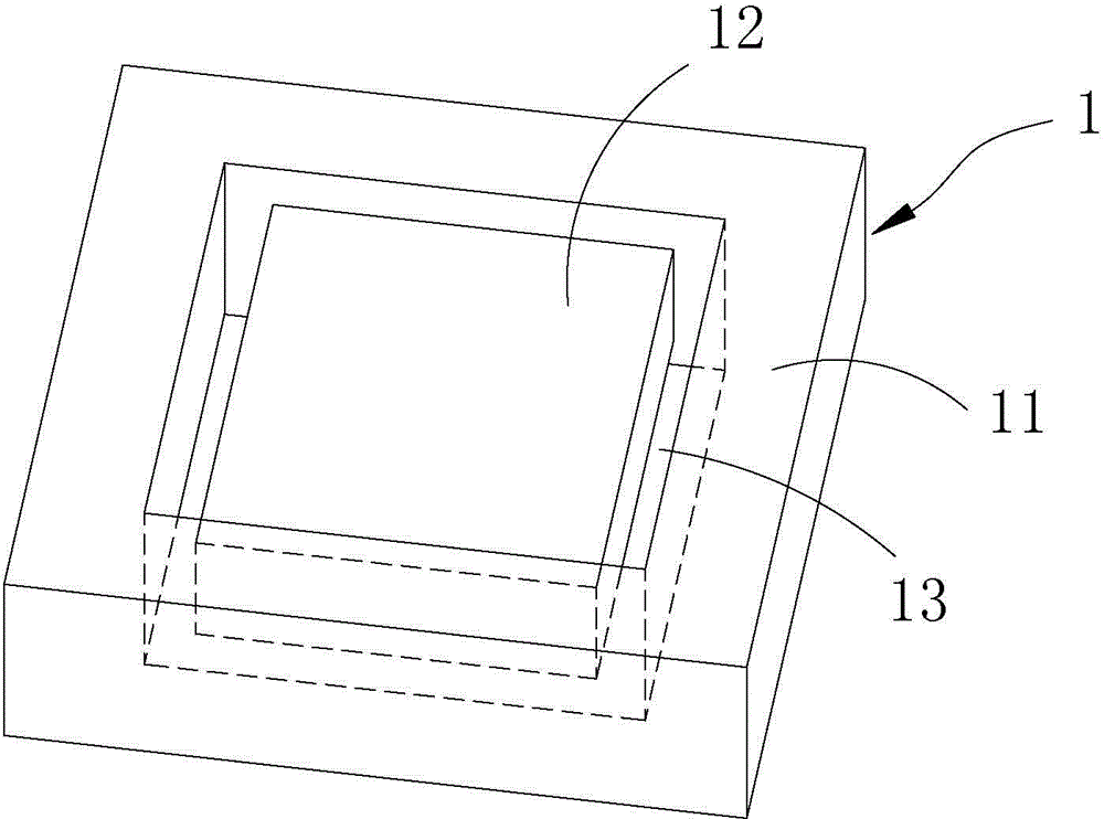
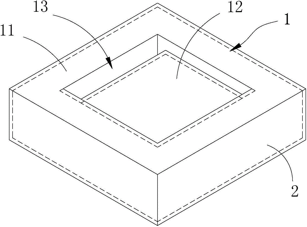
[0051] Step 102, thermosetting production, using the thermosetting process to press the above-mentioned iron core powder into a "day"-shaped powder core (such as figure 2 shown).

[0052] Step 104, sintering production, sintering the above-mentioned pressed "day" shaped powder core, and after low temperature sintering, the "day" shaped powder core is formed into a "day" shaped iron core (powder core sintered body) 1, the T...


PUM


Abstract

The invention discloses a manufacturing method of a chip type inductor. The method comprises the steps of preparing iron core powder; pressing the iron core powder into a powder core in a shape of a Chinese character Ri (sun); sintering the pressed powder core in the shape of the Chinese character Ri (sun) to form an iron core in a shape of the Chinese character Ri (sun); manufacturing an insulation layer on the surface of the iron core after sintering the iron core; manufacturing an electrode layer on the surface of the insulation layer; coiling a coiling part of the iron core with a coil; electrically connecting the coil with the electrode layer; sealing the coil area with glue to form a closed magnetic circuit structure; then exposing the electrode layer to form the chip type inductor after the closed magnetic circuit structure is manufactured.

Description

technical field [0001] The invention relates to an inductor, in particular to a manufacturing method of a chip inductor. Background technique [0002] Inductor is a kind of passive component, which has electronic components that resist any current change. It is composed of a coil wound around a supporting iron core material, and the iron core material can be magnetic or non-magnetic. Inductor is a circuit element made by changing the coil current to produce a change in magnetic flux. It is made according to the phenomenon of the magnetic field. The source of the magnetic field is the flow of charge, which is formed by the current. The alternating current will generate a magnetic field, and the changing magnetic field will induce a current. The ratio of its linear relationship is called inductance. [0003] The traditional combined inductor mainly has an I-shaped iron core of manganese-zinc ferrite, and the coil is wound on the I-shaped iron core, and then the I-shaped iron ...

Claims


Application Information

Patent Timeline
IPC IPC(8): H01F41/00H01F41/02H01F27/29H01R43/16
Inventor 赵宜泰
Owner KUNSHAN MAJI ELECTRONICS
Why Eureka
Try Eureka