Phase-locked loop with correction and correction method thereof

A phase-locked loop and correction loop technology, applied in the field of microelectronics, can solve problems such as difficulty in obtaining high-speed and stable clocks, and impact on clock system performance, and achieve the effects of low power consumption, simple and clear structure, and improved stability

Inactive Publication Date: 2015-06-03
UNIV OF ELECTRONICS SCI & TECH OF CHINA
View PDF4 Cites 8 Cited by
  • Summary
  • Abstract
  • Description
  • Claims
  • Application Information

AI Technical Summary

Problems solved by technology

However, due to noise interference, the impact of clock offset and jitter on system performance is very obvious, and it is difficult to obtain a high-speed and stable clock with a simple oscillator.

Method used


Image

  • Phase-locked loop with correction and correction method thereof
  • Phase-locked loop with correction and correction method thereof
  • Phase-locked loop with correction and correction method thereof

Examples


Embodiment

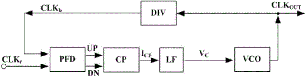
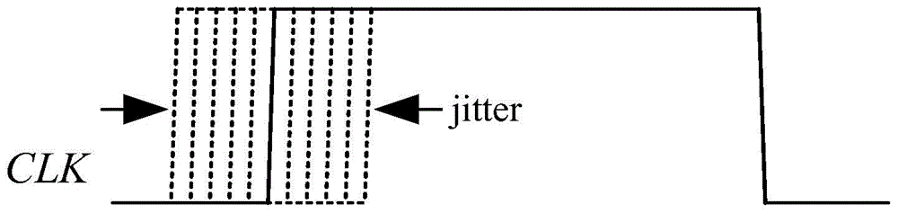
[0031] Such as Figure 5 Shown is a phase-locked loop with correction. After the circuit is powered on, the PLL main loop works normally and tracks the reference clock CLK r The frequency and phase of the lock detector (LD) output signal V LD is low, the correction loop is not started; when the PLL loop is locked, the feedback clock CLK b The frequency and phase of the reference clock CLK r Consistent, but due to different levels of noise in each unit circuit in the PLL loop, the feedback clock CLK b Will exhibit random jitter (such as Figure 6 shown), so after the main loop locks, the lock detector (LD) outputs a signal V LD Change to high level, the correction loop starts to work.

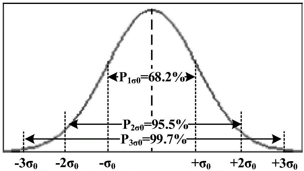
[0032] 2-bit time-to-digital converter (TDC) comparison feedback clock CLK b with reference clock CLK r offset and generate a digital output code. Such as Figure 6 shown, if CLK b Occurs at -σ 0 On the left side, the output code is 00; if CLK b in [-σ 0 ,+σ 0 ] range, the output c...


PUM


Abstract

The invention provides a phase-locked loop with correction and a correction method thereof, which are used for reducing jitter of an output clock of the phase-locked loop. The phase-locked loop with correction is divided into a main loop and a correction loop, wherein the main loop comprises a frequency discriminator / phase discriminator, a charge pump, a low-pass filter, a voltage-controlled oscillator and a frequency divider; the correction loop comprises a lock detector, a time digital converter, two counters, two digital comparators and a digital to analog converter, and the specific connection mode is that a feedback clock and a reference clock are taken as input of the time lock detector and input of the time digital converter; the output of the time digital converter is connected to the input of the first counter and the input of the second counter; the output of the first counter and the output of the second counter are respectively connected to the input of the first comparator and the input of the second comparator, and the outputs of the comparators and the output of the lock detector are connected to the input of the digital to analog converter; the output of the digital to analog converter is connected to the charge pump for controlling the output current of the charge pump.

Description

technical field [0001] The invention belongs to the technical field of microelectronics, relates to a phase-locked loop in the microelectronic technology, in particular to a phase-locked loop with correction and a correction method thereof. Background technique [0002] As the performance of integrated circuits continues to improve, the main frequency of microprocessors is also gradually increasing. Inside the chip, a stable high-frequency clock generation circuit is particularly important. However, due to the interference of noise, the impact of clock offset and jitter on system performance is very obvious, and it is difficult to obtain a high-speed and stable clock with a simple oscillator. Today, in the field of integrated circuits, phase-locking technology is widely used to generate high-speed and high-precision clock signals. [0003] The usual phase-locked loop structure is as figure 1 As shown, it consists of a frequency / phase detector (PFD), a charge pump (CP), a ...

Claims


Application Information

Patent Timeline
Patent Type & Authority Applications(China)
IPC IPC(8): H03L7/099
Inventor 宁宁刘志华李靖刘皓吴霜毅于奇
Owner UNIV OF ELECTRONICS SCI & TECH OF CHINA
Why Eureka
Try Eureka