Supercharge Your Innovation With Domain-Expert AI Agents!

Heavy plate feeder

A plate feeder, heavy-duty technology, applied in the direction of conveyors, conveyor objects, transportation and packaging, etc., can solve the problems that rolling bearings are easily damaged by impact, dust is easy to enter the inside of the bearing, and the current of the motor is unstable, so as to reduce maintenance and maintenance frequency, improve the normal operation cycle, and reduce the effect of maintenance difficulty

Inactive Publication Date: 2015-06-10
TIANJIN WEILI MACHINERY
View PDF8 Cites 4 Cited by
  • Summary
  • Abstract
  • Description
  • Claims
  • Application Information

AI Technical Summary

Problems solved by technology

[0005] First, the upper and lower supporting wheel devices are stuck due to impact damage, lubrication failure and other failures, and they are often shut down for maintenance.
The occurrence of these failures is because the existing heavy-duty apron feeder's upper and lower supporting roller devices use rolling bearings as the slewing support parts of the supporting roller. Because the working environment of the heavy-duty apron feeder is very harsh, such as extra large The impact of materials, a large amount of dust wrapping the supporting wheel device, etc., make the rolling bearing in the supporting wheel very vulnerable to impact damage, and the dust can easily enter the inside of the bearing, causing the rolling bearing to lock
These will cause the supporting wheel to be stuck, serious wear, unstable motor current, power increase and other consequences.
[0006] Second, due to the structural defects of the existing conveying trough, the surface of the lower supporting roller is ground into a deep groove. Due to the appearance of the above-mentioned deep groove, the feeder is easy to cause the lower supporting roller to be stuck during operation, and even cause the lower supporting roller to The wheel is directly scrapped, and this problem is also the most prone to failure of the current heavy-duty apron feeder
For example, a disclosed heavy-duty apron feeder, the patent number is 03270602.2, and the accompanying drawings of the description figure 2 and image 3 , which clearly shows the structure of the existing conveying trough; that is, the existing conveying trough mainly includes the main bearing plate, the upper surface of the main bearing plate is provided with anti-shock square steel, and the lower surface of the main bearing plate is equipped with longitudinal reinforcement Ribs, transverse reinforcing ribs are installed on both sides of the longitudinal and long reinforcing ribs; an upstroke supporting plate is arranged on the lower surface of the transverse reinforcing ribs, outer plates are welded on both sides of the main bearing plate, inner plates are welded on the inner sides of the outer plates, and inner plates are welded on the outer sides. The upper surface of the plate and the upper surface of the inner plate form a plane, which is supported on the lower supporting roller device during the downstroke, because this plane is very narrow, causing the surface of the lower supporting roller to be ground into deep grooves until it is damaged
[0007] The damaged supporting wheel device in the above two problems not only has a short service life, but also is very difficult to replace due to the structural problems of the frame. It is almost necessary to disassemble the whole feeder for maintenance.

Method used


Image

  • Heavy plate feeder
  • Heavy plate feeder
  • Heavy plate feeder

Examples


Embodiment Construction

[0031] In order to further understand the invention content, characteristics and effects of the present invention, the following examples are given, and detailed descriptions are as follows in conjunction with the accompanying drawings:

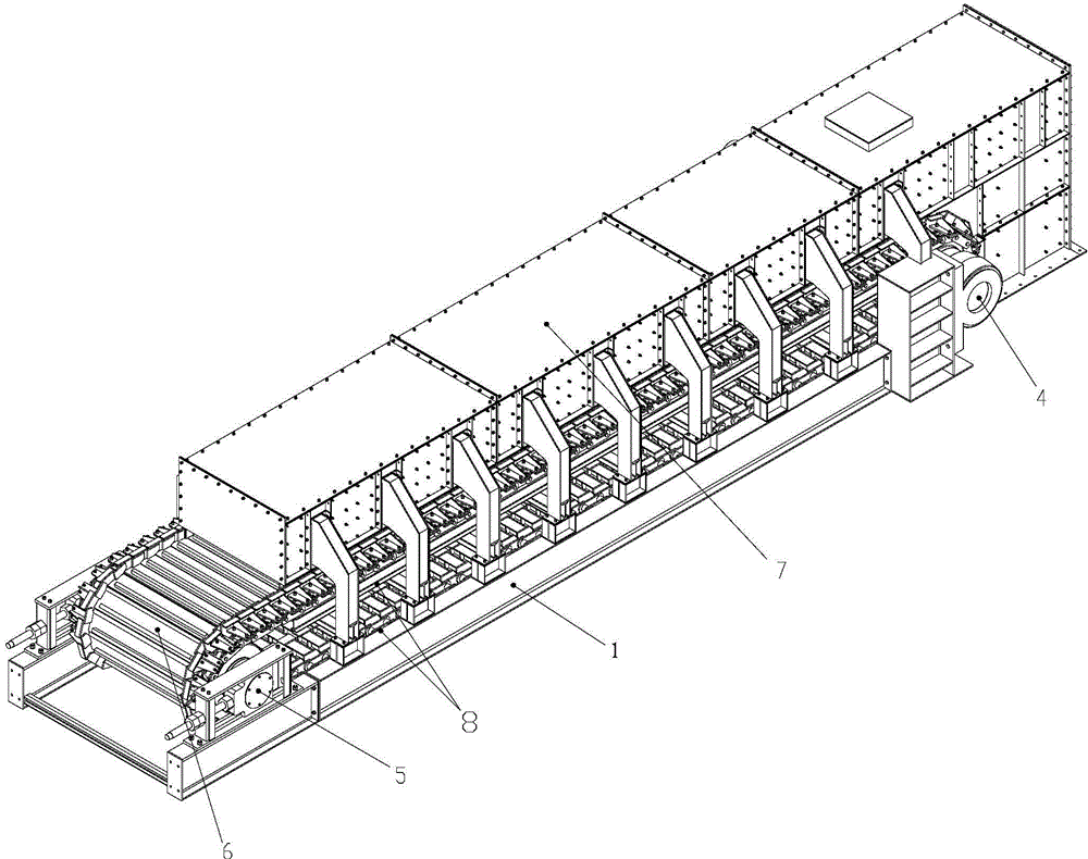
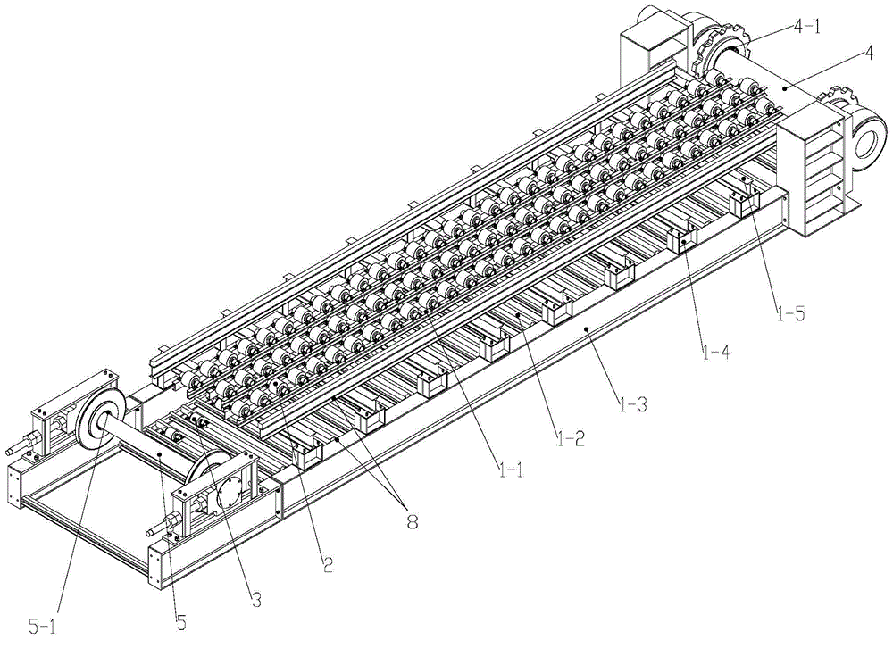
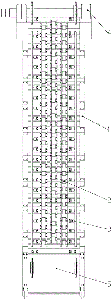
[0032] see Figure 1 to Figure 4 , a heavy-duty apron feeder, mainly including a frame 1, an upper supporting wheel device 2, a lower supporting wheel device 3, a head sprocket driving device 4, a tail sprocket tensioning device 5, a carrying mechanism 6 and a material guide protection device7. Wherein said carrying mechanism 6 is mainly made of conveying chain 6-1 and several conveying troughs 6-2 installed on the conveying chain, and an upper roller device and a lower roller device supporting the carrying mechanism are installed on the frame.

[0033] see Figure 2 to Figure 7 , the structure of the above-mentioned upper supporting wheel device 2 and the lower supporting wheel device 3 is exactly the same. In this embodiment, only the upp...


PUM


Abstract

The invention relates to a heavy plate feeder. The heavy plate feeder comprises a frame, an upper wheel supporting unit, a lower wheel supporting unit, a front sprocket driving unit, a rear sprocket tensioning unit, a conveying mechanism and a feed guide and protection unit. A lower supporting plate is welded to a conveying groove of the conveying mechanism. The upper surface of the supporting plate, the upper surface of an outer side plate and the upper surface of an inner side plate are on the same plane to form a continuous support surface. Solid supporting wheels sleeve support shafts of the upper wheel supporting unit and the lower wheel supporting unit and are provided with shaft holes in the centers. Therefore, the problems that bearings are in serious abrasion and blocked due to impact damage, serious wear abrasion and not-in-time lubrication of the upper wheel supporting unit and the lower wheel supporting unit and accordingly the situation of machine down for troubleshooting is caused are solved, the problem that a lower supporting wheel is blocked due to the fact that the surface of the lower supporting wheel is abraded with deep grooves caused by structural defects of an existing conveying trough is also solved, the normal operating cycle of the product is prolonged, and sections and portions can be replaced separately for greatly reducing maintenance costs and maintenance difficulty.

Description

technical field [0001] The invention belongs to the technical field of apron feeders, in particular to a heavy-duty apron feeder. Background technique [0002] Apron feeder is a continuous transport machine widely used in metallurgy, mining, building materials, ports, coal and chemical industries. It is mainly used to continuously and evenly supply and transfer various bulky and highly abrasive bulk materials from storage bins or transfer hoppers to crushers, batching devices or transportation equipment. It is one of the important and indispensable equipment in ore and raw material processing and continuous production process. [0003] The operating principle of the apron feeder is that high-strength chains are used as traction parts, and the two chains bypass a pair of driving sprockets installed at the head of the machine body and a pair of tensioning sprockets at the tail of the machine body to form a closed operating circuit. Overlapping, heavy-duty conveyor troughs ar...

Claims


Application Information

Patent Timeline
Patent Type & Authority Applications(China)
IPC IPC(8): B65G39/09B65G17/30
CPCB65G39/09B65G17/30
Inventor 李孟江
Owner TIANJIN WEILI MACHINERY
Features
  • R&D
  • Intellectual Property
  • Life Sciences
  • Materials
  • Tech Scout
  • Unparalleled Data Quality
  • Higher Quality Content
  • 60% Fewer Hallucinations
Learn More