
Continuous spray dispersion method of micro/nano dry powder particles

A particle and dry powder technology, which is applied in the direction of conveying bulk materials, conveyors, transportation and packaging, etc., can solve the problems of difficulty in nanoparticle dispersion, small geometric mean deviation, and inapplicable nanoparticle dispersion, etc., to achieve convenient spray dispersion control, Applicable effect

Active Publication Date: 2015-06-10
CHINA JILIANG UNIV
View PDF7 Cites 3 Cited by
  • Summary
  • Abstract
  • Description
  • Claims
  • Application Information

AI Technical Summary

Problems solved by technology

[0004] At present, there are many representative dust generators on the market that actually belong to the "dry" particle dispersion technology, but these particle dispersion equipment have two shortcomings: (1) Most dust generators are for micron-sized particles Developed by dispersion, it is not suitable for nanoparticle dispersion. Due to the influence of particle size, nanoparticle dispersion is more difficult; (2) mainstream dust generators are relatively expensive, and at the same time, a considerable part of the dispersed particle distribution is multimodal distribution, rather than a quasi-lognormal distribution that is unimodal and has a small deviation from the geometric mean
[0005] Recent related research has proved that it is feasible to disperse micron and nano-particles using cheap vacuum generators, but this new method can only last for a few seconds each time, and cannot achieve continuous jet dispersion of particles and precise control of particle concentration

Method used


Image

  • Continuous spray dispersion method of micro/nano dry powder particles
  • Continuous spray dispersion method of micro/nano dry powder particles
  • Continuous spray dispersion method of micro/nano dry powder particles

Examples


Embodiment Construction

[0030] The present invention will be further described below in conjunction with accompanying drawing and example.

[0031] As shown in the figure, the overall embodiment of the present invention is:

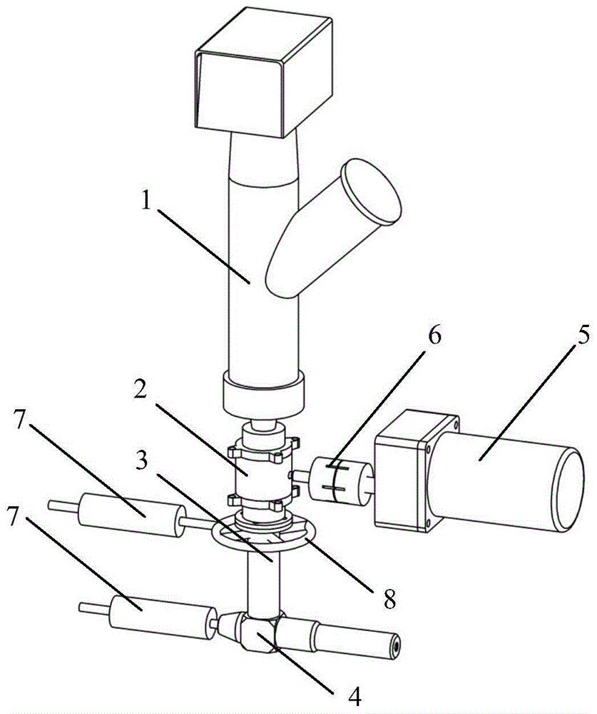
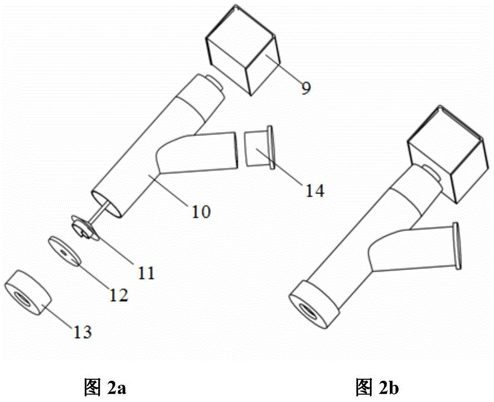
[0032] Put a certain amount of granular powder into the remaining material container 10 from the feeding port of the feeder 1, and slightly smooth it; adjust the speed of the gear motor 5, generally 30rpm or 60rpm can meet the requirements; The gas inlet of 8 is equipped with an air cleaning unit 7, such as a filter cartridge or a high-efficiency filter, to prevent the impure gas from entering the vacuum end of the vacuum generator through the feeder 3 from contaminating the dispersed aerosol; during operation, first open the vacuum generator 4 The upstream valve of the inlet makes the compressed air start to enter the vacuum generator 4, and its vacuum end 27 then starts to generate negative pressure; the feeding rate is set by controlling the speed of the stepping motor 9 of t...


PUM

PropertyMeasurementUnit
diameteraaaaaaaaaa
depthaaaaaaaaaa

Abstract

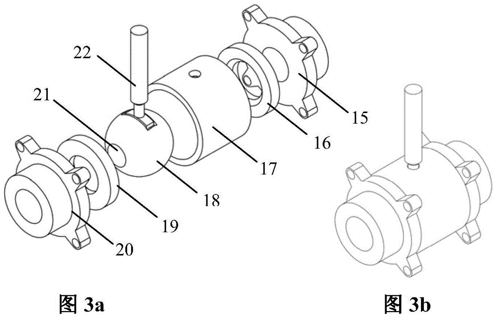
The invention relates to a continuous spray dispersion method of micro / nano dry powder particles. In the continuous spray dispersion method, a vacuum generator is in charge of spray dispersion of the particles; a precision doser is used for precisely controlling the feeding rate; a pressure balancing unit is used for ensuring that the doser can precisely and quantitatively feed a material in an environment with relatively stable pressure; a rotating central shaft of a valve core in the pressure balancing unit is connected with a speed reducing motor through a shaft coupler, the speed reducing motor drives the valve core of the pressure balancing unit, and through regulation of the rotation speed of the motor, different feeding rates and transfer of particles of different materials can be met; after the dry powder particles conveyed by the pressure balancing unit is mixed with purity supplementing gas in a material receiver, the dry powder particles are sucked into the vacuum generator for the spray dispersion under the action of negative pressure at a vacuum end. The continuous spray dispersion method has relatively high applicability; the total concentration of the dispersed particles can be regulated only by regulating the rotation speed of the motor of the doser, and further the rotation speed of a distributor is changed, so that spray dispersion control is very convenient and quick.

Description

technical field [0001] The invention belongs to the technical field of aerosol technology, particle technology and multiphase flow experiment, and relates to a continuous jet dispersion method of dry powder particles. Background technique [0002] Micron and nanoparticle two-phase flow is a common phenomenon in nature, and has been widely used in many fields such as atmospheric environmental science, modern nanomaterial preparation, engineering thermophysics, chemical synthesis, inhalation toxicology, and medical pharmaceuticals. hotspot. As the discrete phase of gas-solid two-phase flow, particles are often required to be in a dispersed state when they are used in these fields, such as simulating atmospheric pollutants-haze, multi-phase jet synthesis of new nanomaterials, (high temperature) spray nanocoatings, thermal power generation systems Combustion of pulverized coal in a medium fluidized bed, long-term toxicology experiments of inhalable particulate matter (submicron...

Claims


Application Information

Patent Timeline
Patent Type & Authority Applications(China)
IPC IPC(8): B65G53/66B65G53/40
Inventor 凃程旭林建忠杜鹏飞张力张沫廖金泽
Owner CHINA JILIANG UNIV
Learn More