Welding structure of missile wing support of solid rocket engine

A solid rocket and welding structure technology, which is applied in the direction of rocket engine devices, machines/engines, mechanical equipment, etc., can solve the problem of inability to effectively release welding residual stress, decrease of external load capacity of wing support, and reduce welding strength of wing support etc. to reduce residual thermal stress, prevent cracks, and improve structural strength

Inactive Publication Date: 2015-06-10
SHANGHAI XINLI POWER EQUIP RES INST
View PDF4 Cites 1 Cited by
  • Summary
  • Abstract
  • Description
  • Claims
  • Application Information

AI Technical Summary

Problems solved by technology

[0007] The problem with the structural form without axial bottom groove is that the residual stress generated during welding cannot be effectively released, and cracks are prone to occur, which reduces the welding strength of the wing support, thereby reducing the ability of the wing support to withstand external loads, resulting in The decline of the reliability of the overall structure of the missile

Method used


Image

  • Welding structure of missile wing support of solid rocket engine

Examples


Embodiment Construction

[0020] The invention will be described in more detail hereinafter with reference to the accompanying drawings showing embodiments of the invention. However, this invention may be embodied in many different forms and should not be construed as limited to the embodiments set forth herein. Rather, these embodiments are provided so that this disclosure will be thorough and complete, and will fully convey the scope of the invention to those skilled in the art. In these drawings, the size and relative sizes of layers and regions may be exaggerated for clarity.

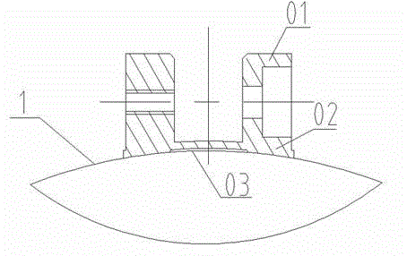
[0021] now refer to figure 1 The welding structure of the solid rocket motor wing support according to the embodiment of the present invention is described in detail. Such as figure 1 As shown, the solid rocket motor wing support welding structure includes a body and a bottom groove 03 located on the lower end surface of the body; the body includes: a base 02 and an ear post 01. The ear post 01 is connected to the base 0...


PUM

PropertyMeasurementUnit
Heightaaaaaaaaaa
Widthaaaaaaaaaa
Widthaaaaaaaaaa

Abstract

The invention discloses a welding structure of a missile wing support of a solid rocket engine. The welding structure comprises a body and a bottom groove positioned in the lower end surface of the body, wherein the body comprises a base and an ear column, and the ear column is connected with the base through a step surface; a first end surface of the ear column is used as a mounting surface of a missile wing, and the missile wing is mounted in an axial groove in the center of the ear column; a second end surface opposite to the first end surface is a concave cambered surface, and the diameter of the second end surface is the same as that of a combustion chamber casing; two straight flanges of the second end surface are welded to the combustion chamber casing, so that the connection between the missile wing support and the combustion chamber casing is realized; the bottom groove penetrating through the second end surface is formed in the second end surface, and the bottom groove is parallel to a welding joint between the second end surface and the combustion chamber casing. According to the welding structure adopted by the invention, compared with the prior art, the welding structure has the advantages and the benefits that residual thermal stress caused by weld is reduced, cracks are avoided, the structural strength of the missile wing support is improved, the qualified rate of handmade argon arc welding is increased, and the technology process is optimized.

Description

[0001] technical field [0002] The invention relates to the technical field of solid rocket motors, in particular to a welding structure for wing supports of solid rocket motors. [0003] Background technique [0004] The combustion chamber casing is one of the important parts in the engine structure. It is a storage tank filled with solid propellant and a place where the propellant burns. At the same time, it is also a component of the missile body. On the premise of meeting the requirements of the engine development mission statement, in the design of the engine combustion chamber shell, various load requirements during the flight test should be considered in the structural design to improve the reliability of the missile's overall structure. [0005] As the external part of the combustion chamber shell, the wing support mainly bears the external load of the missile wing, and its working condition is relatively severe. At the same time, as the main load-bearing compo...

Claims


Application Information

Patent Timeline
IPC IPC(8): F02K9/32
Inventor 乐浩麦玲娄永春刘凤潘丽华俞鑫王一奇
Owner SHANGHAI XINLI POWER EQUIP RES INST
Why Eureka
Try Eureka