
Method for calibrating numerical simulation results of inner flow field in centrifugal pump

A numerical simulation, internal flow field technology, applied in pump control, non-variable-capacity pumps, machines/engines, etc., can solve the problems of high price, low specific speed, and the difficulty of transparent materials to withstand large pump stress, and achieve short cycle times. , Low experimental cost, avoid the effect of reopening the mold

Active Publication Date: 2015-06-10
CHINA JILIANG UNIV
View PDF5 Cites 23 Cited by
  • Summary
  • Abstract
  • Description
  • Claims
  • Application Information

AI Technical Summary

Problems solved by technology

[0007] However, so far, the relevant research using PIV is limited to centrifugal pumps with low specific speed and small size. This is mainly because when PIV is applied to the measurement of the internal flow field of the pump, the wall of the area to be measured must be transparent. , so that the CCD camera can capture particle images. For small pumps, although the cost is expensive, the pump casing and even the impeller can still be processed with transparent materials to meet the test requirements of PIV, and the cost is acceptable; for large pumps As far as the pump is concerned, it will be very expensive and impractical to process the same transparent whole machine, and the general transparent material is also difficult to withstand the stress caused by the internal flow field of the large pump
Therefore, for large-size, high-power, high-speed centrifugal pumps, no experimental research on the application of PIV technology has been seen.

Method used


Image

  • Method for calibrating numerical simulation results of inner flow field in centrifugal pump
  • Method for calibrating numerical simulation results of inner flow field in centrifugal pump
  • Method for calibrating numerical simulation results of inner flow field in centrifugal pump

Examples


Embodiment Construction

[0037] The present invention will be further explained below with reference to the drawings and examples.

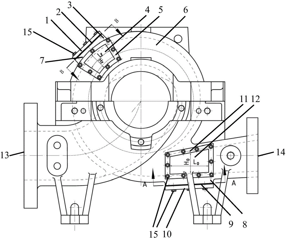
[0038] Such as Figure 1-3 As shown, taking a double-suction centrifugal pump as an example, the specific implementation of the present invention is:

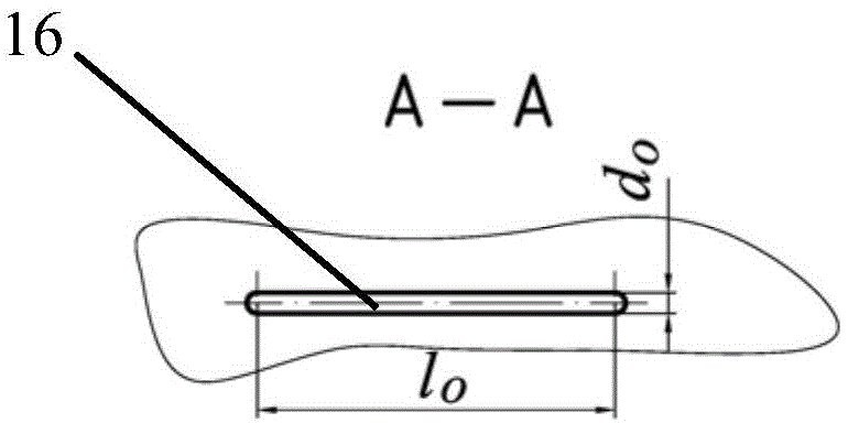
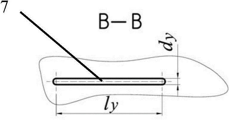
[0039] First of all, the partial mechanical modification of the prototype pump body of the double-suction centrifugal pump is carried out to meet the requirements of PIV measurement and lay a good foundation for obtaining the flow field in the pump. The transformation means that there are 1~3 fan-shaped windows 4 approximately centered on the central axis of rotation of the impeller in the tip clearance of the pressurized water chamber of the volute of the centrifugal pump, and an approximately rectangular and rectangular window is opened on the upstream side of the outlet 14 of the pressurized water chamber. A window 12 that is close to parallel to the center rotation surface of the centrifugal pump impeller. The windows ar...


PUM


Abstract

The invention relates to a method for calibrating the numerical simulation results of an inner flow field in a centrifugal pump. The method comprises the following steps: performing mechanical reformation in such specific regions as a tip clearance on a centrifugal pump prototype and the exit of a pumping chamber, so as to ensure that the specific regions are transparent and visible; utilizing the PIV technology to measure the transient whole-flow-field velocity distribution in the specific regions, and obtaining such statistics characteristic parameters as the regional average velocity in the specific regions; conducting contrastive analysis on the PIV experimental results in the specific regions and the numerical simulation results, including the overall distribution characteristics of a velocity vector, the average velocity, and other statistics characteristic parameters; quantitively checking the accuracy of the numerical simulation results, and repeatedly modifying the key parameters, such as a fluid domain, a grid, an initial condition and a calculation model, in a numerical simulation process to correct the numerical simulation results, thereby achieving the aim of calibrating the numerical simulation results of the inner flow field in the centrifugal pump. The method is low in experimental cost, short in period, and higher in applicability and feasibility.

Description

Technical field [0001] The invention relates to a method for calibrating numerical simulation results of the internal flow field of a centrifugal pump. Background technique [0002] The pump is a general-purpose mechanical equipment with a large volume and a wide range of energy consumption. According to statistics from the China Pump Association, the total annual output value of the national pump industry in 2010 was more than 100 billion yuan, and 20-25% of the national power generation each year was consumed in pump products. Among all pump products, centrifugal pumps have the advantages of simple structure, convenient use and maintenance, large flow, and high lift. They are used in petrochemical, mining, metallurgy, electric power, urban water supply and drainage, sewage treatment and other industries. Efficiency is of key significance to the realization of national energy conservation and emission reduction targets. Take the high-power double-suction centrifugal pump as an...

Claims


Application Information

Patent Timeline
Patent Type & Authority Applications(China)
IPC IPC(8): F04D15/00
CPCF04D15/0088F05D2260/81
Inventor 包福兵李楠狄辉彬凃程旭
Owner CHINA JILIANG UNIV
Features
  • Generate Ideas
  • Intellectual Property
  • Life Sciences
  • Materials
  • Tech Scout
  • Unparalleled Data Quality
  • Higher Quality Content
  • 60% Fewer Hallucinations
Learn More