Refrigerator

A technology for refrigerators and air inlets, which is applied in the field of refrigeration, and can solve the problems of large room temperature difference, large cold air resistance, and small air volume for fresh-keeping, and achieve good fresh-keeping effects, ensure uniformity, and avoid frosting.

Inactive Publication Date: 2015-06-10
SUZHOU SAMSUNG ELECTRONICS CO LTD +1
View PDF8 Cites 13 Cited by
  • Summary
  • Abstract
  • Description
  • Claims
  • Application Information

AI Technical Summary

Problems solved by technology

[0004] The front side of the fresh-keeping room refers to the part close to the door body. Due to the low heat insulation effect of the door body side, the heat load on the front side is large and the temperature is high. However, because the temperature of the cold air generated by the evaporator is very low, its temperature is close to -20°C, therefore, when the cold air is transmitted from the rear side to the front side through the cooling air duct, the temperature near the air inlet on the rear side of the cooling air duct cools down quickly and the temperature is low; the outer wall surface of the cooling air duct near the rear side is prone to frost
At the same time, because the top cooling air duct is a closed air duct, the cross-sectional area is relatively small, the air volume is small, and the cold air resistance is large. When the cold air reaches the front side of the fresh-keeping room, the cooling loss of the cold air is large, resulting in insufficient cooling capacity at the front side of the fresh-keeping room and slow cooling. As a result, the temperature difference between the front side and the rear side of the fresh-keeping room is large, and the temperature in the fresh-keeping room is uneven, which affects the fresh-keeping effect of the fresh-keeping room

Method used


Image

  • Refrigerator
  • Refrigerator
  • Refrigerator

Examples


Embodiment Construction

[0023] The core of the present invention is to provide a refrigerator, which can ensure uniform temperature in the fresh-keeping chamber of the refrigerator and ensure the fresh-keeping effect of the fresh-keeping chamber.

[0024] In order to enable those skilled in the art to better understand the solution of the present invention, the present invention will be further described in detail below in conjunction with the accompanying drawings and specific embodiments.

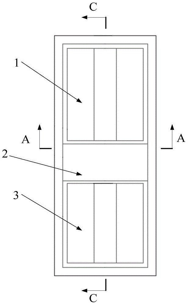
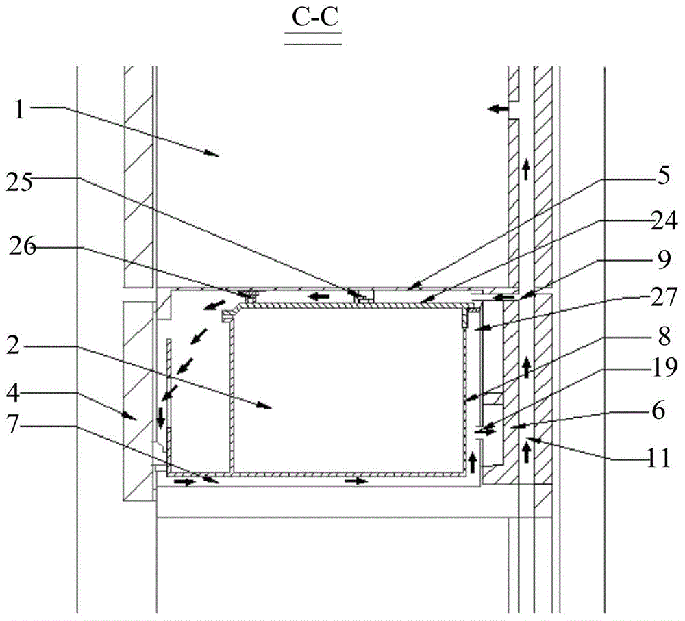
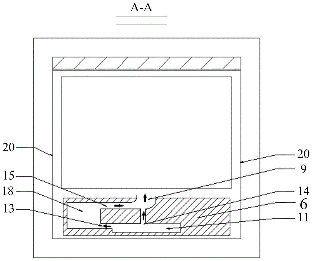
[0025] Please refer to Figure 1 to Figure 5 , figure 1 It is a schematic structural diagram of a refrigerator in a specific embodiment provided by the present invention, figure 2 for figure 1 The structural schematic diagram of the local structure of the C-C sectional view shown, image 3 for figure 1 The structural schematic diagram of the local structure of the A-A sectional view shown, Figure 4 for figure 1 The structural schematic diagram of the rear side sectional view of the fresh-keeping room sho...


PUM


Abstract

The invention discloses a refrigerator which comprises a refrigerating chamber and a preservation chamber with a cooling air duct, wherein the cooling air duct comprises an air inlet duct and an air return duct; the air inlet duct is provided with an air mixing duct; an air inlet of the air mixing duct is communicated with a first air duct of which the cold air temperature is lower than the target temperature of the preservation chamber, and is also communicated with a second air duct of which the cold air temperature is higher than that of the first air duct; an air outlet of the air mixing duct is communicated with an air inlet of the preservation chamber; the air return duct of the cooling air duct is communicated with an air return inlet of the preservation chamber. According to the refrigerator, the air mixing duct is used for mixing low-temperature cold air in the first air duct and cold air in the second air duct to form mixed air of which the temperature is slightly lower than the target temperature of the preservation chamber, so that the mixed air can be prevented from being frosted in a transmission process; in addition, the volume of the formed mixed air is large, and the temperature of the mixed air is close to the target temperature of the preservation chamber, so that the temperature difference of the front and rear sides of the preservation chamber can further be reduced, and the temperature uniformity of the preservation chamber can be ensured.

Description

technical field [0001] The invention relates to the technical field of refrigeration, in particular to a refrigerator. Background technique [0002] Along with improving day by day of people's living standard, refrigerator has become a kind of electric appliance in common use. Refrigerators are usually provided with fresh-keeping chambers for keeping the freshness and flavor of fruits and vegetables to the greatest extent. [0003] In order to keep the fresh-keeping room at a low temperature, it needs to be cooled. In the prior art, the fresh-keeping room of a refrigerator uses cooling air ducts for radiation cooling to ensure the low temperature of the fresh-keeping room. This kind of fresh-keeping room is a relatively closed environment. Cooling air ducts are arranged on the top and rear of the fresh-keeping room, and the cooling fan is used to transport the cold air generated by the evaporator to the cooling air duct. Radiative cooling. Among them, the cooling of the f...

Claims


Application Information

Patent Timeline
Patent Type & Authority Applications(China)
IPC IPC(8): F25D11/02F25D17/04
CPCF25D11/02F25D17/045
Inventor 王玉芝陈劲松
Owner SUZHOU SAMSUNG ELECTRONICS CO LTD
Why Eureka
Try Eureka