
Thermo-mechanical coupling loading method for thermal strength tests

A technology of thermal coupling and thermal strength, applied in the direction of applying stable tension/pressure to test the strength of materials, etc., can solve the problems of unsatisfactory heating belt, large influence of rubber, low thermal conductivity, etc.

Inactive Publication Date: 2015-06-10
CHINA AIRPLANT STRENGTH RES INST
View PDF5 Cites 19 Cited by
  • Summary
  • Abstract
  • Description
  • Claims
  • Application Information

AI Technical Summary

Problems solved by technology

[0003] The resistance wire heating belt can heat the test piece below 300°C. If a higher temperature thermal test is carried out, the heating belt cannot meet the requirements.
And because the surface of the heating belt is made of insulating material, the thermal conductivity is low, the heating rate is slow, and the control followability is poor, which cannot meet the requirements of the large temperature rise rate test.
The use of quartz tube heaters can meet the test requirements of large temperature rise rate and high temperature, and the control followability is good, but it uses thermal radiation non-contact heating, which conflicts with the arrangement of the water bladder, and the high temperature has a greater impact on the rubber that constitutes the shell of the water bladder. large, it should not be used
The water injection and pressurization of the water bladder realizes the loading of the load on the contact area of ​​the test piece surface as a uniform load, and it is impossible to realize the loading of unequally distributed load on the surface of the test piece

Method used


Image

  • Thermo-mechanical coupling loading method for thermal strength tests
  • Thermo-mechanical coupling loading method for thermal strength tests
  • Thermo-mechanical coupling loading method for thermal strength tests

Examples


Embodiment

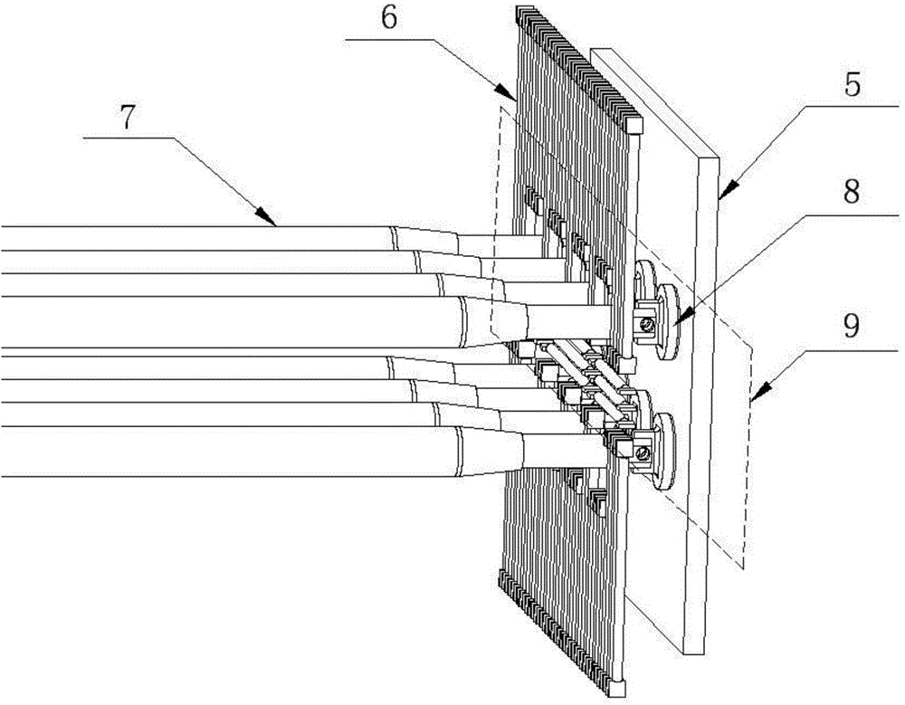
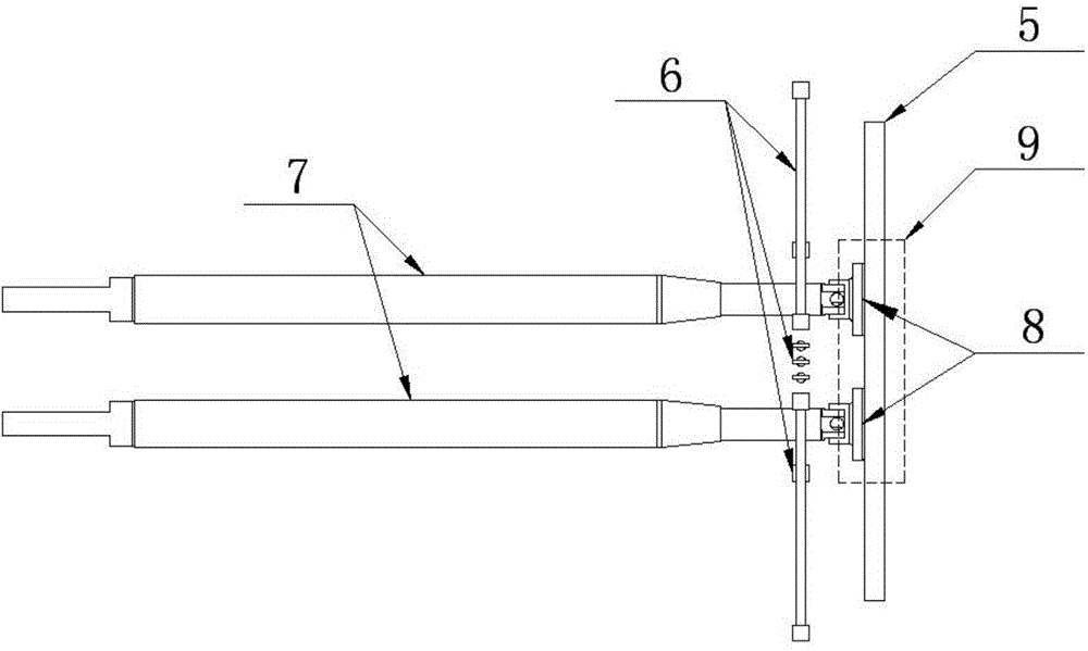
[0037] see figure 2 , image 3 and Figure 4 , which is a schematic diagram, a front view and a side view of the loading effect of the quartz lamp tube combined with the push rod pushing the loading block of the present invention, including the test piece 5, the quartz lamp tube 6, the push rod 7, the loading block 8 and the test piece loading area 9. The quartz lamp tubes 6 are arranged, and the quartz lamp tubes 6 are controlled in partitions. The arrangement range of the quartz lamp tubes is required to cover the edge of the test piece 5 and leave a space in the loading area 9 of the test piece. Connect the ejector rod 7 to the loading block 8, and pass through the area where the quartz lamp tubes 6 are arranged so that the loading block 8 is in uniform contact with the test piece 5. During the test, according to the load distribution requirements of the test piece loading area 9, the loading blocks are coordinated to load, so that the quartz lamps in each area under hig...


PUM


Abstract

The invention provides a thermo-mechanical coupling loading method for thermal strength tests, which can be used for achieving high temperature and large temperature rise rate and simulating unequally distributed loads. The technical scheme is as follows: the method comprises the following steps: arranging a quartz burner in front of a test piece loading area, wherein a gap is formed between the quartz burner and the test piece loading area, and a gap area is reserved in the arrangement area of the quartz burner; hinging a loading block at the front end of a mandril, wherein the loading block penetrates through the gap area of the arrangement area of the quartz burner and props against the surface of the test piece loading area; heating the test piece loading area via thermal radiation by using the quartz burner; and loading mechanical load on the test piece loading area by using the loading block.

Description

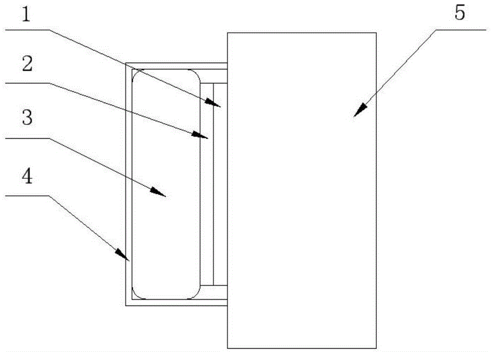
technical field [0001] The invention belongs to the technical field of thermal strength of aircraft structures, and in particular relates to a force-thermal coupling loading method. Background technique [0002] In the surface distributed load force thermal coupling test applied to the outer area of ​​the test piece, the resistance wire heating belt and the water bag are generally used for thermal load and force load loading, please refer to figure 1 , which is a schematic diagram of the loading effect of the existing resistance wire heating belt combined with the water bladder. The heating belt 1 is arranged close to the test piece 5, and the test piece 5 is heated by contact. The heat insulation layer 2 is between the water bag 3 and the heating belt 1 to prevent the water bag 3 from being affected by the temperature. The water bag carrying shell 4 plays a position-limiting effect on the water bag 3 to prevent its deformation and expansion. [0003] The resistance wire ...

Claims


Application Information

Patent Timeline
IPC IPC(8): G01N3/18
Inventor 李世平丛琳华陆琳蒋军亮
Owner CHINA AIRPLANT STRENGTH RES INST
Learn More