
Atomic magnetic sensor for magnetometer and method of removing detection dead zones of magnetometer

A magnetic sensor and magnetometer technology, applied in magnetic resonance measurement and other directions, can solve the problems of inability to detect optical signals, affecting the size of detection signals, and inability to adapt to real-time detection of mobile platforms, so as to improve reliability and eliminate detection blind spots.

Active Publication Date: 2015-06-10
PEKING UNIV
View PDF7 Cites 25 Cited by
  • Summary
  • Abstract
  • Description
  • Claims
  • Application Information

AI Technical Summary

Problems solved by technology

[0004] Although the traditional laser optically pumped atomic magnetometer can measure the magnetic field, due to the change of the angle between the direction of the light and the direction of the detection magnetic field, the size of the detection signal is affected. In a specific direction, the optical signal cannot be detected, resulting in a dead zone. This situation makes the traditional laser optically pumped atomic magnetometer unable to adapt to the real-time detection of the magnetic field by the mobile platform.

Method used


Image

  • Atomic magnetic sensor for magnetometer and method of removing detection dead zones of magnetometer
  • Atomic magnetic sensor for magnetometer and method of removing detection dead zones of magnetometer

Examples


Embodiment Construction

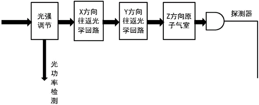
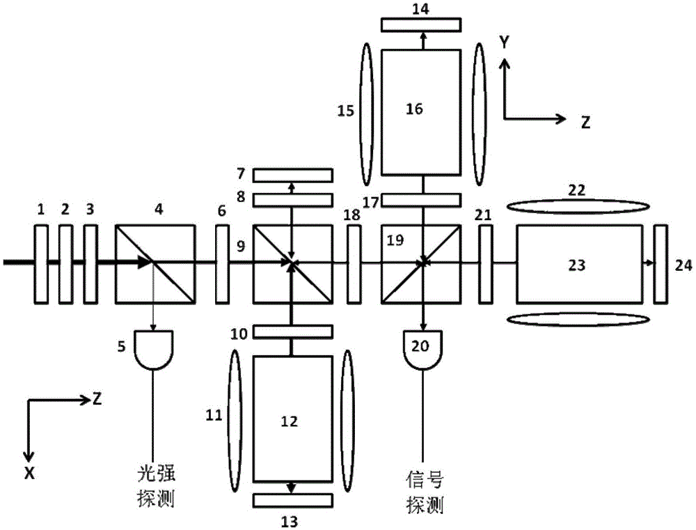
[0027] The present invention will be further described in detail below with reference to the accompanying drawings. It is necessary to point out that the following specific embodiments are only used to further illustrate the present invention and cannot be understood as limiting the scope of protection of the present invention. Those skilled in the art can Some non-essential improvements and adjustments have been made to the present invention based on the above-mentioned content of the invention.

[0028] Such as figure 1 Shown is a schematic diagram of the main functional modules of the present invention, which includes a light intensity adjustment module without polarization influence. A part of the light is split and can be used to detect changes in optical power to stabilize the power of the laser, including X-direction round-trip optics The circuit forms the X-axis magnetic detection, including the Y-direction reciprocating optical circuit, forming the Y-axis magnetic detecti...


PUM


Abstract

The invention provides an atomic magnetic sensor for a laser optical pump magnetometer. The atomic magnetic sensor includes two round-trip optical loops and an atomic absorption chamber in the third direction, wherein the round-trip optical loops and the atomic absorption chamber are arranged on a laser optical path in sequence, and the two round-trip optical loops are spatially perpendicular to each other. Each optical loop is provided with an optical shaft and includes an atomic absorption air chamber used for converting a beam of laser perpendicular to the direction of the optical shaft to circularly polarized light spreading in the direction of the optical shaft and enabling the circularly polarized light to be perpendicular to the direction of the optical shaft again after conducting optical pumping on atoms in the atomic absorption chamber. The atomic magnetic sensor further includes a photoelectric detector, wherein an optical signal is converged to the photoelectric detector through the three round-trip optical loops spatially perpendicular to each other and the atomic absorption chamber in the third direction and is converted to an electric signal. The atomic magnetic sensor can remove the dead zone of the laser optical pump magnetometer in magnetic detection and meanwhile achieves highly sensitive measurement of magnetic field. The invention further provides a method of removing the detection dead zone of the magnetometer.

Description

Technical field [0001] The invention relates to the technical field of optical pumping magnetometers, in particular to an atomic magnetic sensor used in a magnetometer and a method for eliminating the detection blind zone of the magnetometer. Background technique [0002] Magnetometer is a general term for magnetic measuring instruments. High-sensitivity magnetic measurement technology has extensive and important applications in biomedicine, geophysics, space exploration, military and national defense and other fields. At present, there are significant differences in the level of magnetic measurement research at home and abroad. The foreign advanced level magnetometer has far exceeded our country in terms of sensitivity index, etc. Therefore, it is of strategic significance to independently develop a high-sensitivity magnetometer. The optically pumped atomic magnetometer is one of the more mature high-sensitivity magnetometers. Among them, the laser optically pumped atomic magn...

Claims


Application Information

Patent Timeline
Patent Type & Authority Applications(China)
IPC IPC(8): G01R33/26
Inventor 郭弘彭翔王海东公韦
Owner PEKING UNIV
Learn More