
Cleaning machine with switch box structure

A switch box and cleaning machine technology, applied in the field of cleaning machines, can solve the problems of large space requirements for the whole machine, high production costs, and too many parts, and achieve the effects of compact structure, simple assembly, and reduced manufacturing costs

Active Publication Date: 2015-06-10
SUZHOU KINGCLEAN PRECISION MACHINERY
View PDF4 Cites 6 Cited by
  • Summary
  • Abstract
  • Description
  • Claims
  • Application Information

AI Technical Summary

Problems solved by technology

As a result, there is a great demand for the space of the whole machine, and it will also cause disadvantages such as cumbersome structure, too many parts, complicated assembly, and high production cost.

Method used


Image

  • Cleaning machine with switch box structure
  • Cleaning machine with switch box structure
  • Cleaning machine with switch box structure

Examples


Embodiment

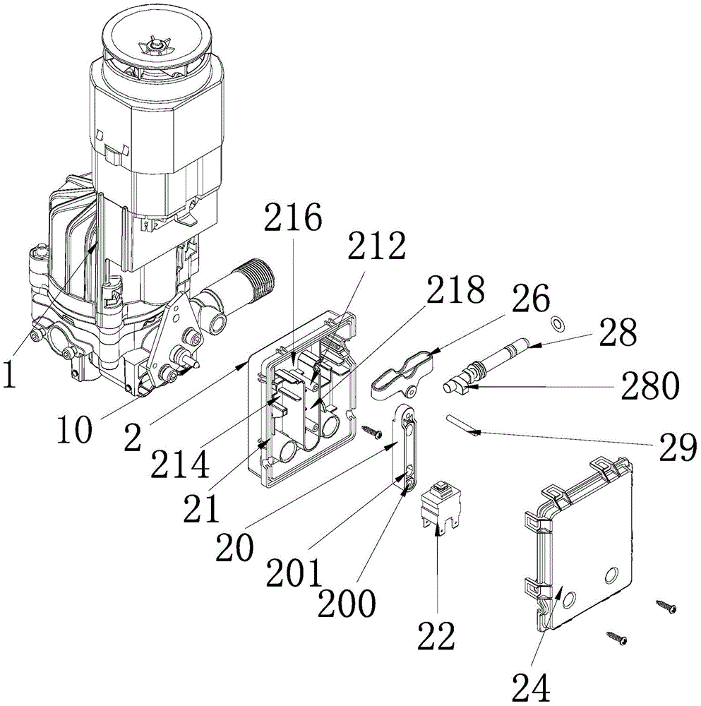
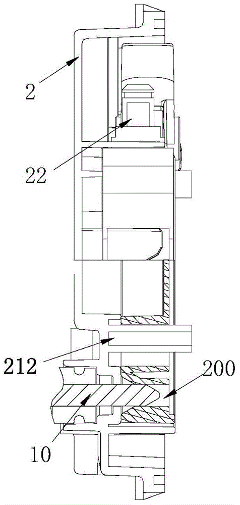
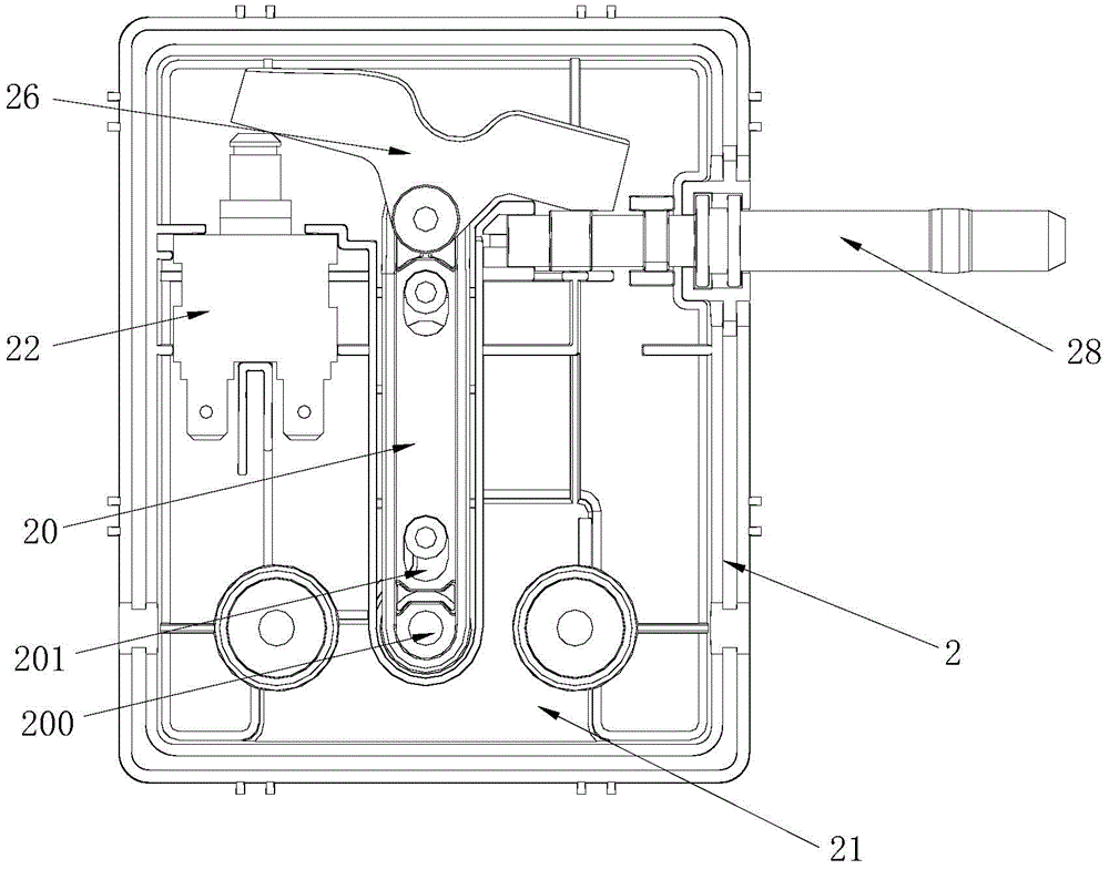
[0027] Example: such as Figure 1-7 As shown, the present invention provides a specific embodiment of a washing machine with a switch box structure, which includes a motor pump assembly 1, a switch box 2 fixed on the motor pump assembly 1, and a switch box 2 fixed on the motor pump assembly 1 and in The piston rod 10 that reciprocates along the first direction in the switch box 2, wherein the switch box 2 includes a switch push rod 20 that cooperates with the piston rod 10 and reciprocates in the second direction, the fulcrum is arranged on the switch push rod 20, and both ends can The switch rocker arm 26 that rotates around the fulcrum, the switch 22 that is located on one side of the switch push rod 20 and can be in contact with one end of the switch rocker arm 26, is located on the other side of the switch push rod 20 and can be in contact with the other end of the switch rocker arm 26 contact with the rotary rod 28 . Wherein the switch push rod 20 and the switch rocker...


PUM


Abstract

The invention discloses a cleaning machine with a switch box structure. The cleaning machine is characterized by comprising a motor pump component, a switch box fixed on the motor pump component and a piston rod fixed on the motor pump component and reciprocating in the switch box along the first direction; the switch comprises a switch push bar matched with the piston bar and reciprocating in the second direction, a switch rocker with the rotating shaft arranged on the switch push bar and two ends capable of rotating around the rotating shaft, a switch located on one side of the switch push bar and in abutted contact with one end of the switch rocker and a spinning handle located on one side of the switch push bar and capable of being in abutted contact with the other end of the switch rocker. Mounting, fixing and connecting modes of double switches are not needed to be considered during assembling and fixing, and large space is saved for the complete machine which is compact in structure, easy to assemble, high in platformization and low in manufacturing cost.

Description

technical field [0001] The invention relates to a cleaning machine with a switch box structure. Background technique [0002] As we all know, high-pressure cleaners often turn on and off the gun frequently during use. In order to better extend the service life of the whole machine and save the user from the trouble of manually switching the power supply due to short-term shutdown, it is often equipped with an automatic shutdown mechanism. When the water gun is turned off, the body stops moving, and when the water gun is turned on, the power supply can be automatically turned on, and the whole machine starts to work. The working principle of the automatic shutdown mechanism is as follows: connect a main switch and a A micro switch, the micro switch is fixed in the micro switch box, and the micro switch box is fixed in the pump assembly. When the gun is shut down, the micro switch is triggered and disconnected by the principle of reciprocating movement of the piston rod in th...

Claims


Application Information

Patent Timeline
IPC IPC(8): H01H3/32H01H3/26B08B13/00
CPCB08B3/02B08B13/00B08B2203/02H01H3/32
Inventor 倪祖根
Owner SUZHOU KINGCLEAN PRECISION MACHINERY
Learn More