
Compressed sensing point-by-point scanning camera for inside of divided array blocks

A point-by-point scanning and array block technology, applied in the parts and electrical components of TVs and color TVs, can solve the problems of single control method, low frame rate, and inability to control the flipping of micromirrors freely and flexibly, saving storage resources. , the effect of improving the speed of imaging

Inactive Publication Date: 2015-06-10
SICHUAN UNIV
View PDF4 Cites 6 Cited by
  • Summary
  • Abstract
  • Description
  • Claims
  • Application Information

AI Technical Summary

Problems solved by technology

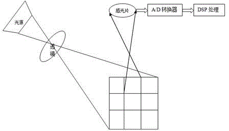
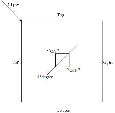
This DLP-based system has a single control method and a low frame rate. Any image input by the user will be displayed by the system in 256 grayscales, and the flip of the micromirror cannot be freely and flexibly controlled.
[0005] In laser modulation applications, it is required to be able to freely control the flipping time of the binary micromirror; in compressed imaging / correlated imaging / quantum imaging applications, the flipping time of the micromirror is required to be fast and at equal intervals, and at the same time, it is required to be able to give Synchronous signal to facilitate CCD image acquisition; In the field of laser lithography, there are mainly "stepping lithography" and "flying lithography" exposure methods in the world, both of which require the absolute locking function and synchronization function of the micromirror The "flying lithography" method also needs the support of high frame rate to achieve the best lithography effect; and in other advanced binary optical applications, etc., users cannot operate the DMD as they like.

Method used


Image

  • Compressed sensing point-by-point scanning camera for inside of divided array blocks
  • Compressed sensing point-by-point scanning camera for inside of divided array blocks
  • Compressed sensing point-by-point scanning camera for inside of divided array blocks

Examples


Embodiment Construction

[0012] The present invention scans the digital micromirror array camera point by point, and the specific steps are as follows:

[0013] The DMD array is divided into several small squares in advance, and the lens group casts the scene light onto the DMD array. By controlling the digital micromirror on the DMD array to flip point by point, the scene light is scanned block by point, that is, in each small square Compressed sampling is carried out respectively. Then the original signal is reconstructed according to the reconstruction algorithm, and the DMD array scans the reconstructed scene image point by point and reflects it to the photosensitive sheet for imaging. The invention utilizes the point-by-point scanning of the DMD array to improve the imaging speed. It is a new shooting method with great potential application value, which breaks through the bottleneck of Shannon's sampling theorem, and accurately reconstructs the original image from a small number of sampling measu...


PUM


Abstract

The invention provides a compressed sensing point-by-point scanning camera for the inside of divided array blocks. The camera comprises an object light source, a lens group, a DMD (Digital Mirror Device) array, a photographic plate, an A / D converter and a DSP (Digital Signal Processor). The DMD array is divided into a plurality of small square blocks in advance; the lens group shoots scenery light rays to the DMD array; the divided point-by-point scanning to the scenery light rays is realized by controlling a digital micromirror on the DMD array to turn point by point, that is, compressed sampling is respectively performed in each small square block. Original signals are reconstructed according to a reconstruction algorithm; the DMD array reflects the reconstructed scenery image subjected to point-by-point scanning on the photographic plate for imaging. The imaging speed is accelerated by means of the point-by-point scanning of the DMD array; a new shooting method with great potential application value is provided; the bottleneck of Shannon's sampling theorem is broken; an original image is reconstructed precisely from a small quantity of sampling and measuring values; the acquisition and compression of traditional data become one and the storage resource is saved.

Description

technical field [0001] The invention belongs to the field of image acquisition and imaging, and in particular relates to a point-by-point scanning camera for compressive sensing within block array blocks. Background technique [0002] In practical applications, people use high-speed sampling to process broadband signals. According to the Nyquist sampling theorem, in order not to lose the information of the signal, it must be sampled at a sampling frequency higher than twice the bandwidth of the signal. In order to reduce the cost of storage and transmission, the compression method is used to represent the signal with fewer data bits, a large amount of unimportant data is discarded, and the information data actually provided only accounts for a small part of the actual sampled data. This data is then transferred to the desired location and decompressed to recover useful information from the signal. [0003] In recent years, the emerging compressive sensing theory (compressi...

Claims


Application Information

Patent Timeline
IPC IPC(8): H04N5/225H04N5/232
Inventor 李智李健向中辉
Owner SICHUAN UNIV
Learn More