Al technical title is built by PatSnap Al team. It summarizes the technical point description of the patent document.
A suction device and thrombus technology are applied in the field of thrombus suction device and suction device to achieve the effect of convenient and quick operation and reducing surgical complications.
Inactive Publication Date: 2015-06-17
陈勇
View PDF0 Cites 4 Cited by
Summary
Abstract
Description
Claims
Application Information
AI Technical Summary
This helps you quickly interpret patents by identifying the three key elements:
Problems solved by technology
Method used
Benefits of technology
Problems solved by technology
Because some thrombi are hard and larger than the lumen of the catheter, they are easy to block the lumen of the catheter, resulting in a small number of thrombus per aspiration, and repeated removal of the catheter sheath or large-lumen catheter, reinsertion of the catheter sheath or large-lumen catheter, In order to completely extract the thrombus, such repeated operations will lead to low suction efficiency, prolong the operation time, and increase the incidence of complications, such as intimal injury, excessive blood loss, and postoperative infection.
[0003] At present, there is no special surgical instrument for aspiration of thrombus. Introducer sheaths or large lumen catheters are often used to aspirate thrombus. Operating time, causing great inconvenience to the operation
Method used
Image
Click on the blue label to locate the original text in one second.
Reading with bidirectional positioning of images and text.
Examples
Embodiment Construction
[0014] The specific embodiments of the present invention are given below with reference to the accompanying drawings, which are used to further describe the structure of the present invention.
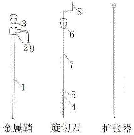
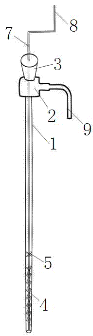
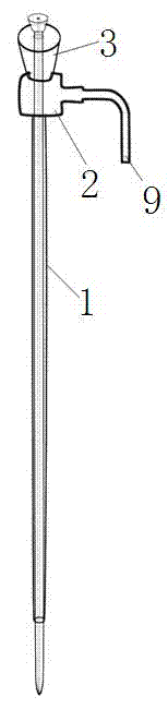
[0015] A kind of thrombus suction device of the present embodiment, refer to Figure 1-3 , including a metal sheath, a rotary cutter and a dilator, the metal sheath includes a metal helical tube 1, one end of the metal helical tube 1 is equipped with a side tube 2, and one end of the side tube 2 is movably connected with an anti-reflux cap-3; The rotary cutter includes a crank handle 7, a spiral diversion groove 4 is provided at an end far away from the handle 8, and an anti-reflux cap 2 6 is provided at an end close to the handle 8, and the middle of the reverse flow cap 2 6 and the spiral diversion groove 4 is installed There is a blade 5; the metal sheath is used in conjunction with a dilator to realize the effect of a common metal long sheath to dilate blood vessels, and the metal ...
PUM
Abstract
The invention relates to an aspiration device, in particular to a thrombus aspiration device, and belongs to the technical field of medical instrument structures. The thrombus aspiration device comprises a metal sheath, a rotary cutter and an expander. The metal sheath comprises a metal spiral pipe, a side pipe is arranged at one end of the metal spiral pipe, and one end of the side pipe is movably connected with a first backflow preventing cap. The rotary cutter comprises a crank, a spiral flow guide groove is formed in the end, away from the handle, of the rotary cutter, a second backflow preventing cap is arranged at the end, close to the handle, of the rotary cutter, and a blade is arranged between the second backflow preventing cap and the spiral flow guide groove. The thrombus aspiration device can replace an original long metal sheath, the expander is withdrawn, the rotary cutter is fed in, the thrombus aspiration device is formed, the side pipe generates negative pressure through pumpback of an injector, thrombus is made to enter the metal sheath, the rotary cutter is rotated, the thrombus is conveyed to move into a lumen under the combined action of the rear driving force of the flow guide groove and the negative pressure, the middle blade cuts the thrombus into small blocks, the thrombus is sucked out of the side pipe, the situation that large thrombus blocks block the pipe cavity, and consequently the aspiration process is interrupted is avoided, operation efficiency is improved, and operative complications are reduced.
Description
Technical field [0001] The present invention involves a suction device. Specifically, the thrombosis absorbing device is the field of medical device structure technology. Background technique [0002] During the intervention surgery of lower limb vein or cavity venous thrombosis, the tube sheath or large cavity ducts need to be used to pump blood thrombus.Due to the hard texture of some thrombus and larger volume than the pipe cavity, it is easy to block the pipe cavity, resulting in a small amount of thrombosis each time, and it is necessary to repeatedly remove the tube sheath or large cavity ducts, then inserted the duct sheath or large cavity duct.In order to pull out all the thrombus, this repeated operation can cause the efficiency of the suction, which extend the operation time of the surgical operation, and the incidence of complications also increases accordingly, such as endometrial damage, excessive blood loss, and postoperative infection. [0003] At present, there i...
Claims
Application Information
Patent Timeline
Application Date:The date an application was filed.
Publication Date:The date a patent or application was officially published.
First Publication Date:The earliest publication date of a patent with the same application number.
Issue Date:Publication date of the patent grant document.
PCT Entry Date:The Entry date of PCT National Phase.
Estimated Expiry Date:The statutory expiry date of a patent right according to the Patent Law, and it is the longest term of protection that the patent right can achieve without the termination of the patent right due to other reasons(Term extension factor has been taken into account ).
Invalid Date:Actual expiry date is based on effective date or publication date of legal transaction data of invalid patent.