
Road rainwater grating well loop and method for constructing pavement structure layer comprising well loop

A rainwater grate and well ring technology is applied in the construction of pavement structure layers and in the field of road rainwater grate, which can solve the problems that the surface asphalt concrete is not easy to be integrated into one, easy to generate muck and waste, waste materials, etc. It is not easy to achieve Disease, simple structure, the effect of increasing anchoring depth

Active Publication Date: 2015-06-17
BEIJING BRIDGE RUITONG MAINTENANCE CENT +1
View PDF7 Cites 1 Cited by
  • Summary
  • Abstract
  • Description
  • Claims
  • Application Information

AI Technical Summary

Problems solved by technology

[0003] (1) "Excavating the underlying asphalt concrete within the installation range of the well circle" not only wastes materials, but also easily generates muck during the excavation process;
[0004] (2) The height of the well circle is 40mm, and the clear height of the asphalt concrete on the pressurized layer of the fixed well circle is only 28mm, and because cement concrete or cement mortar is generally used in the expansion well, it is not easy to integrate with the asphalt concrete on the surface layer, and the asphalt concrete of the surface layer is not easy to be integrated. Under the action of load, it will lead to the occurrence of diseases;
[0005] (3) After the well is expanded, it is necessary to wait for the block mortar or cast-in-situ cement concrete used for the expansion to reach the working strength after 3 to 5 days before starting the paving of the surface layer of asphalt concrete, so the entire construction period is long

Method used


Image

  • Road rainwater grating well loop and method for constructing pavement structure layer comprising well loop
  • Road rainwater grating well loop and method for constructing pavement structure layer comprising well loop
  • Road rainwater grating well loop and method for constructing pavement structure layer comprising well loop

Examples


Embodiment Construction

[0036] Embodiments of the present invention will be further described in detail below in conjunction with the accompanying drawings and examples. The following examples are used to illustrate the present invention, but should not be used to limit the scope of the present invention.

[0037] In the description of the present invention, it should be noted that the terms "center", "longitudinal", "transverse", "upper", "lower", "front", "rear", "left", "right", " The orientations or positional relationships indicated by "vertical", "horizontal", "top", "bottom", "inner" and "outer" are based on the orientations or positional relationships shown in the drawings, and are only for the convenience of describing the present invention and Simplified descriptions, rather than indicating or implying that the device or element referred to must have a particular orientation, be constructed and operate in a particular orientation, and thus should not be construed as limiting the invention. ...


PUM


Abstract

The invention relates to the technical field of town road construction and provides a road rainwater grating well loop and a method for constructing a pavement structure layer comprising the well loop. The road rainwater grating well loop is simple in structure and convenient to install. The anchoring depth of a grating well is increased through the well loop, under-layer bituminous concrete does not need to be excavated or repaired during installation, paving of under-layer bituminous concrete around the rainwater grating well can be achieved at a time, in this way, the rainwater grating well is anchored firmly, the integrity of the road surface around the rainwater grating well is high, quality is guaranteed, and damages are unlikely to occur. Furthermore, due to the fact that excavation and repair of under-layer bituminous concrete are avoided, materials and cost are saved. Finally, due to the fact that surface-layer bituminous concrete can be paved immediately after under-layer bituminous concrete is paved, construction time can be reduced by at least three to five days, and the road rainwater grating well loop is especially suitable for quick paving of town roads.

Description

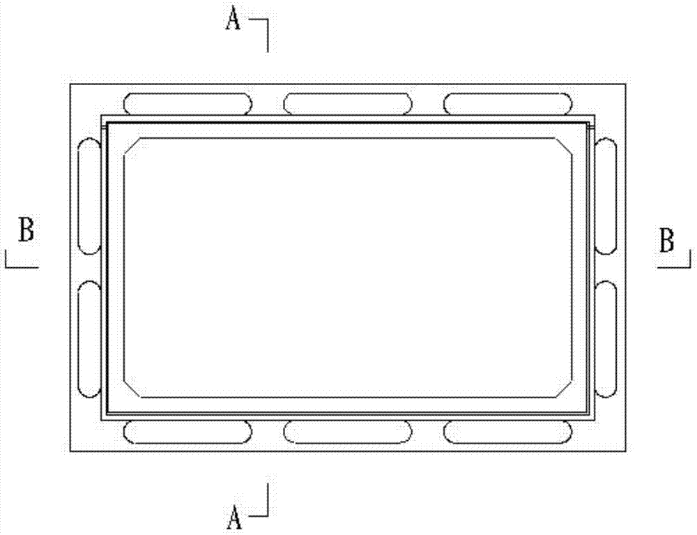
technical field [0001] The invention relates to the technical field of urban road construction, in particular to a road rainwater grate and a construction method for a pavement structure layer including the grate. Background technique [0002] Rainwater grate wells are generally installed on urban roads. Although rainwater grate wells are generally less affected by vehicle loads on the roadside, most inspection wells will still have diseases around them during use, which will affect the appearance of the road and driving safety. Rainwater grate wells in the prior art, taking nodular cast iron rainwater grate wells as an example, please refer to the structure of the well ring Figure 1-3 . The construction method of the pavement structure layer near the well circle is as follows: pavement base construction → paving the bottom asphalt concrete → excavating the bottom asphalt concrete within the installation range of the well circle → expanding the well and placing the well cir...

Claims


Application Information

Patent Timeline
IPC IPC(8): E03F5/04E03F5/06E03F3/06
CPCE01C9/00E01C2201/065E03F5/06
Inventor 魏丽胡世金王鹏飞王斌赵忠磊
Owner BEIJING BRIDGE RUITONG MAINTENANCE CENT
Learn More