Supercharge Your Innovation With Domain-Expert AI Agents!

Thermal transfer catalytic heat dissipation method

A heat dissipation method and heat transfer technology, used in heat transfer modification, heat exchange equipment, heat exchanger fixing, etc., can solve the problems of heat transfer bottlenecks and barriers, limited effectiveness, waste of raw materials, etc.

Inactive Publication Date: 2015-06-17
CY D ENG CO LTD
View PDF12 Cites 0 Cited by
  • Summary
  • Abstract
  • Description
  • Claims
  • Application Information

AI Technical Summary

Problems solved by technology

[0003] In terms of the above-mentioned used heat dissipation mechanism, since the thermal conductivity of the glue is small, the used method uses a high heat dissipation insulating layer (which has a large heat conductivity) to replace the glue, but due to the bottleneck of heat transfer and the The barrier does not occur at the interface between the heat source and the heat sink, but at the interface between the heat sink and the air. Since there is a very large heat transfer drop at this interface (that is, the heat transfer of the heat sink is large, but the heat transfer of the air is small), Although the used heat dissipation mechanism uses a high heat dissipation insulating layer with a large thermal conductivity to replace the glued body in an attempt to improve the heat transfer efficiency, but when the heat is transferred to the space between the heat sink and the air through the heat transfer path in the heat sink, the heat will be lost due to heat transfer. The huge drop in performance results in the heat backflow of the heat transfer path in the heat sink, thus creating a bottleneck and barrier for heat transfer
Therefore, the heat dissipation mechanism that has been used is an ineffective method, because the placement of a high thermal conductivity layer between the two helps to improve heat transfer, but the effect is limited, because the fundamental heat transfer bottleneck and barrier, there is no Therefore, the problem of poor heat dissipation cannot be effectively improved; and in addition to the above-mentioned shortcomings, the arrangement of the heat dissipation fin body will simultaneously cause increased heat dissipation costs, increase the volume and weight of the equipment, and waste raw materials.

Method used


Image

  • Thermal transfer catalytic heat dissipation method
  • Thermal transfer catalytic heat dissipation method
  • Thermal transfer catalytic heat dissipation method

Examples


Embodiment Construction

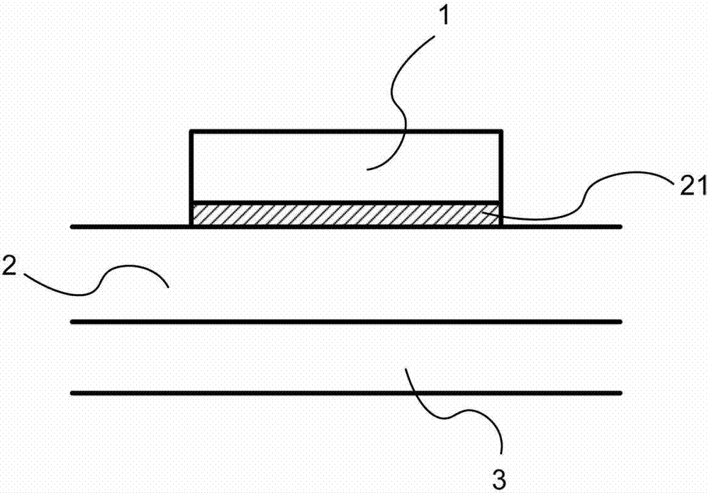
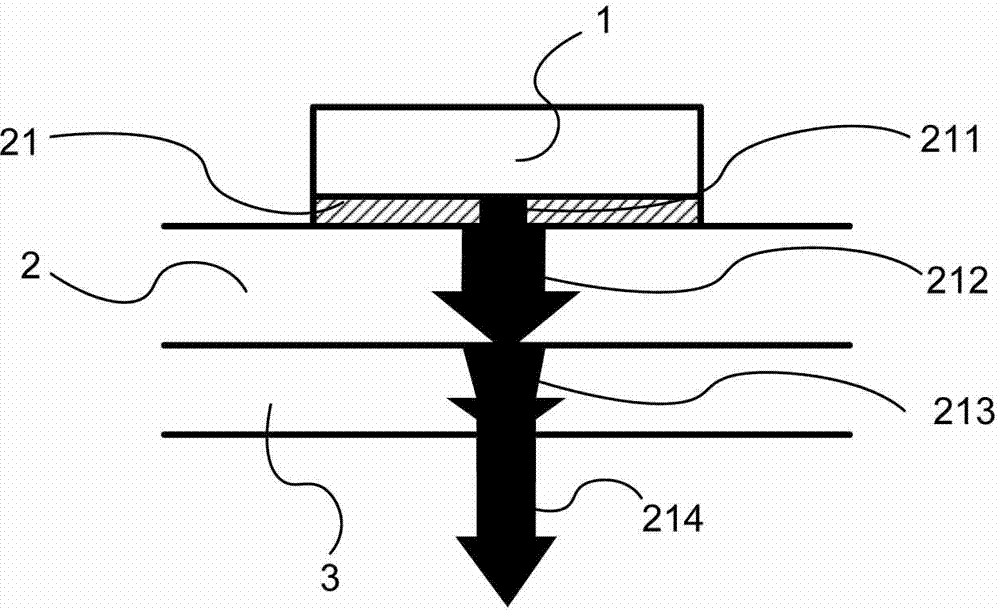
[0026] Please refer to FIG. 1 and FIG. 2 , which are respectively a schematic cross-sectional view of the first embodiment of the present invention and a schematic view of the heat transfer state of the first embodiment of the present invention. As shown in the figure: the present invention is a heat transfer catalytic heat dissipation method, which is provided with a heat transfer interface 2 on a heat source 1, and a six-membered ring carbon-based nano-carbon heat dissipation film 3 is provided on at least one side of the heat transfer interface 2 , so that after the heat transfer interface 2 absorbs the heat source, the six-membered ring carbon-based nano-carbon heat dissipation film 3 dissipates heat.

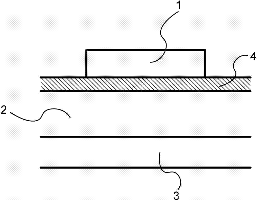
[0027] One surface of the heat transfer interface 2 is combined with the heat source 1, and the six-membered ring carbon-based nanocarbon heat dissipation film 3 is combined with the other surface of the heat transfer interface 2 (that is, the side of the heat transfer inter...


PUM


Abstract

A thermal transfercatalytic heat dissipation method is disclosed, comprises steps of disposing a thermal transfer interface on a heat source; and disposing a carbon nanoparticles which have a hexagonal carbon ring geometry based heat dissipation film on at least a face of the thermal transfer interface, so that the hexagonal carbon ringed nanometer heat dissipation film dissipates the heat source after the thermal transfer interface absorbs the heat source, so that the heat is directed effectively to the ambient through the film, avoiding a thermal transfer drop between the thermal transfer interface and the air, and achieving in that a thermal transfer effectiveness is promoted, a thermal transfer bottleneck is effectively reduced, heat dissipation fins are saved, a heat dissipation cost is largely reduced, a volume and weight is reduced, a consumption of the raw material is reduced and a purpose of energy saving and carbon reduction is achieved.

Description

technical field [0001] The invention relates to a heat transfer catalytic heat dissipation method, especially a method that can use a six-membered ring carbon-based nano-carbon heat dissipation film to effectively guide heat transfer to the air, so as to avoid the heat transfer gap between the heat transfer interface and the air, and achieve Improve heat transfer efficiency, effectively reduce heat transfer bottlenecks, eliminate the need for heat dissipation fins, greatly reduce heat dissipation costs, reduce volume and weight, reduce raw material consumption, and energy-saving and carbon-reducing heat transfer catalytic heat dissipation methods. Background technique [0002] The generally used heat dissipation mechanism is to use a heat dissipation glue or a high thermal conductivity layer, which is placed between a heat sink and a heat source, and further provided with heat dissipation fins on the heat sink, so as to use the heat sink to dissipate heat. [0003] In terms ...

Claims


Application Information

Patent Timeline
Patent Type & Authority Applications(China)
IPC IPC(8): H05K7/20H01L23/373
CPCF28F13/00F28F2013/006F28F2255/20F28F2275/025
Inventor 卢鸿智杨仲宾
Owner CY D ENG CO LTD
Features
  • R&D
  • Intellectual Property
  • Life Sciences
  • Materials
  • Tech Scout
  • Unparalleled Data Quality
  • Higher Quality Content
  • 60% Fewer Hallucinations
Learn More