SCR denitrification control system and method for heating furnace flue gas

A control system and heating furnace technology, applied in chemical instruments and methods, multiple fluid ratio control, separation methods, etc., can solve the problems of petrochemical process heating furnaces that have no practical application, and achieve the effect of avoiding production costs.

Active Publication Date: 2017-03-08
BEIJING BOHUITONG S & T DEV
View PDF5 Cites 1 Cited by
  • Summary
  • Abstract
  • Description
  • Claims
  • Application Information

AI Technical Summary

Problems solved by technology

Although SCR denitrification technology has been widely used in flue gas denitrification of various large-scale coal-fired boilers, with good effect and stable operation, but due to the particularity of petrochemical process heating furnaces, it has no practical application in flue gas denitrification of petrochemical process heating furnaces.

Method used


Image

  • SCR denitrification control system and method for heating furnace flue gas
  • SCR denitrification control system and method for heating furnace flue gas

Examples


Embodiment 1

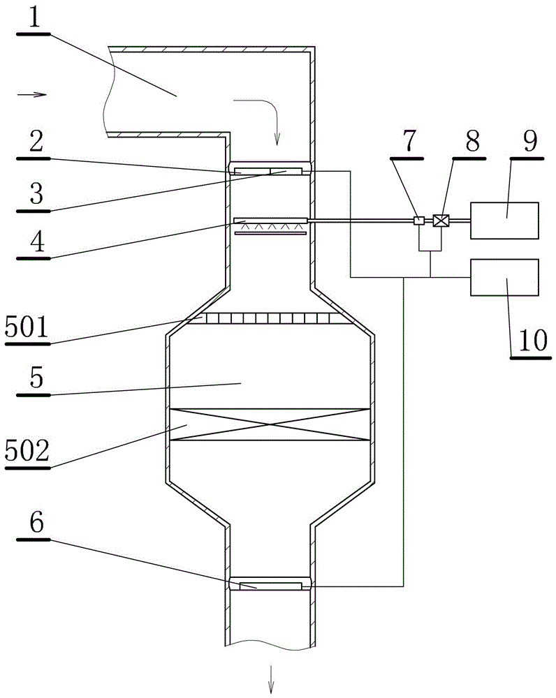
[0023] This embodiment is a SCR denitrification control system for heating furnace flue gas, such as figure 1 shown. The system described in this embodiment includes: an SCR denitrification reactor 5 installed on the heating grate flue 1, a flue gas flow sensor 2 installed at the entrance of the denitrification reactor, an inlet flue gas NOx content sensor 3, and an ammonia spray grid grid 4, the outlet flue gas NOx content sensor 6 installed at the outlet of the denitrification reactor, the ammonia injection grid is connected with the ammonia source 9 pipeline through the ammonia flow regulating valve 8, the ammonia injection grid and An ammonia flow sensor 7 is arranged between the ammonia flow regulating valves, the flue gas flow sensor, the inlet flue gas NOx content sensor, the outlet flue gas NOx content sensor, the ammonia flow regulating valve, the ammonia flow sensor and the controller 10 electrical connections ( figure 1 Electrical connections are indicated by thin...

Embodiment 2

[0034] This embodiment is an improvement of the first embodiment, and is a refinement of the first embodiment on ammonia gas flow detection. An ammonia pressure sensor and an ammonia temperature sensor are also provided between the ammonia injection grid and the ammonia flow regulating valve described in this embodiment.

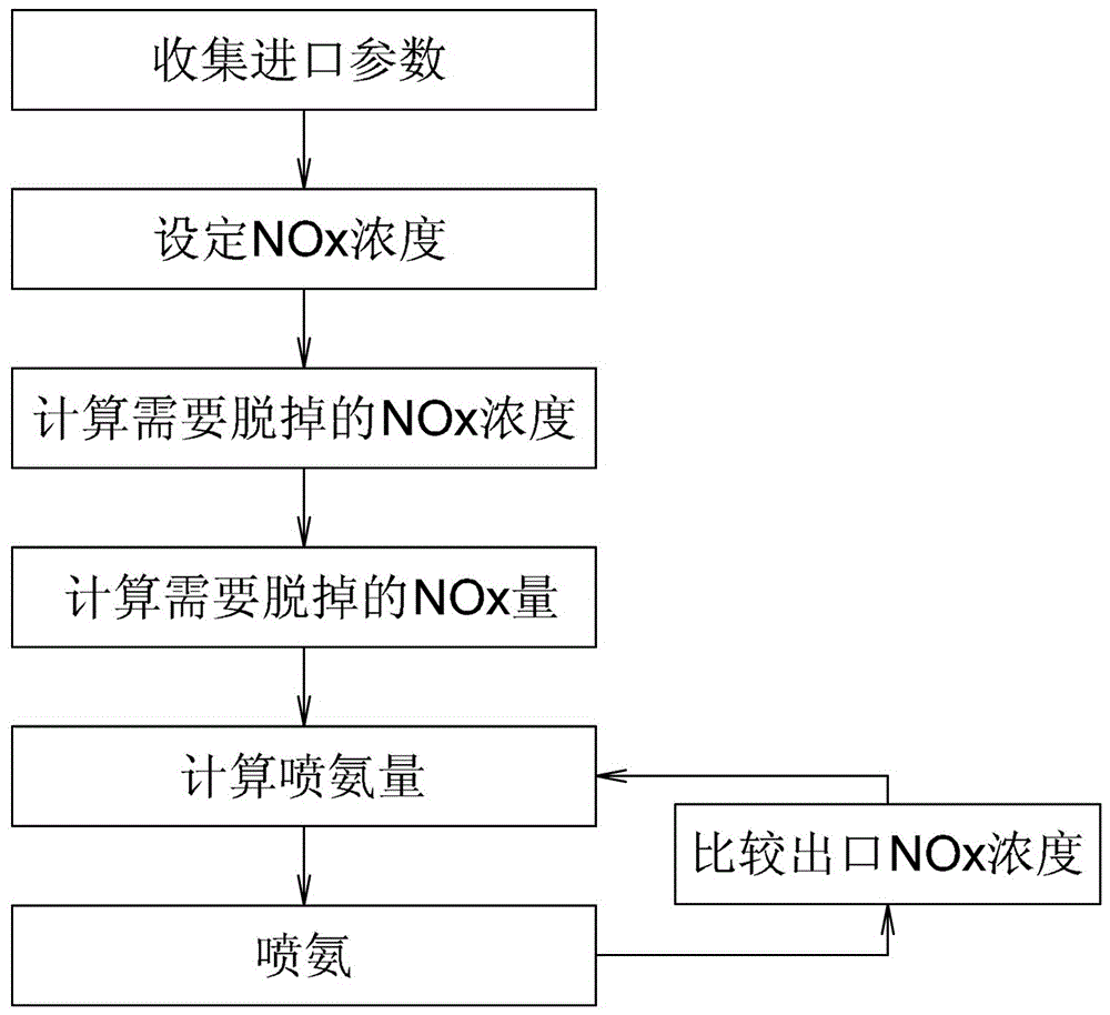
[0035] In this embodiment, the ammonia gas pressure sensor and the ammonia gas temperature sensor are arranged between the ammonia injection grid and the ammonia gas flow regulating valve. The ammonia gas flow is used as the measured value of the control loop after the density correction is carried out by pressure and temperature. The ammonia nitrogen molar ratio is function of denitrification efficiency. The denitrification efficiency is calculated based on the NOx content at the reactor inlet and a given NOx content at the reactor outlet.

[0036] The calculation process of ammonia nitrogen molar ratio is as follows:

[0037] (1) Detect the NOx parameter...

Embodiment 3

[0043] This embodiment is an improvement of the first embodiment, and is a refinement of the first embodiment on the controller. The controller described in this embodiment is a PID.

[0044]To control the NOx concentration in the flue gas, if it is controlled through a functional relationship, a large amount of data is needed to support it, and it is very laborious to find the functional relationship. Therefore, using PID control is a good choice.


PUM


Abstract

The invention relates to an SCR denitration control system and an SCR denitration control method of heating furnace flue gas. The system comprises a flue gas flow sensor, an inlet flue gas NOx content sensor, an ammonia spraying grating, and an outlet flue gas NOx content sensor, wherein the ammonia spraying grating is connected with an ammonia source pipeline through an ammonia flow regulating valve, an ammonia flow sensor is arranged between the ammonia spraying grating and the ammonia flow regulating valve; the flue gas flow sensor, the inlet flue gas NOx content sensor, the outlet flue gas NOx content sensor, the ammonia flow regulating valve, and the ammonia flow sensor are electrically connected with a controller. The flue gas flow sensor and the NOx content sensors are used for monitoring the concentration of NOx in the flue gas passing through an SCR denitration reactor, the ammonia flow regulating valve is regulated in real time through the controller, so that the ammonia sprayed from the ammonia spraying grating is sufficiently reacted with the NOx in the flue gas, the condition that the excessive NOx is discharged to pollute the environment is avoided, and the condition of excessively consuming the ammonia to increase the production cost is avoided.

Description

technical field [0001] The invention relates to an SCR denitrification control system and method for heating furnace flue gas, which is an environmental protection system and process method, and is a system and process method specially applied to SCR denitrification of heating furnace flue gas in petrochemical process. Background technique [0002] Heating furnaces for petrochemical processes are widely used in oil refineries and chemical plants. It is a combustion chamber surrounded by refractory materials, which is used to heat the working fluid by using the heat generated by burning natural gas or gas. Flue gas is produced during the combustion process of heating furnaces in petrochemical processes. The flue gas has the characteristics of small gas volume, complex flue gas composition due to the influence of fuel components, and low concentration of nitrogen oxides in the flue gas. According to environmental protection standards, it is necessary to take denitrification t...

Claims


Application Information

Patent Timeline
Patent Type & Authority Patents(China)
IPC IPC(8): B01D53/90B01D53/56G05D11/13
Inventor 刘莹孟立新孙书伟田国忠周磊
Owner BEIJING BOHUITONG S & T DEV
Why Eureka
Try Eureka