Method for machining circular hole alloy steel cage with inner-and-outer double fore shafts

A processing method and technology of alloy steel, which is applied in the processing field of structural bearing cages, can solve problems such as high wear rate of milling cutters, failure to fit into the outer casing, and difficulty in ensuring the angle, so as to improve production efficiency and improve surface roughness. , The effect of reducing the processing cycle

Inactive Publication Date: 2015-06-24
AVIC HARBIN BEARING
View PDF3 Cites 22 Cited by
  • Summary
  • Abstract
  • Description
  • Claims
  • Application Information

AI Technical Summary

Problems solved by technology

[0010] The purpose of the present invention is to solve the unqualified surface roughness of the pocket hole of the cage, the high wear rate of the drill bit and the milling cutter, the low machining accuracy of the pocket hole of the cage, the instability of the size of the pocket hole and the size o

Method used


Image

  • Method for machining circular hole alloy steel cage with inner-and-outer double fore shafts
  • Method for machining circular hole alloy steel cage with inner-and-outer double fore shafts
  • Method for machining circular hole alloy steel cage with inner-and-outer double fore shafts

Examples


specific Embodiment approach 1

[0046] Specific implementation mode 1: The processing method of an alloy steel cage with inner and outer double locking round holes in this embodiment is carried out according to the following steps:

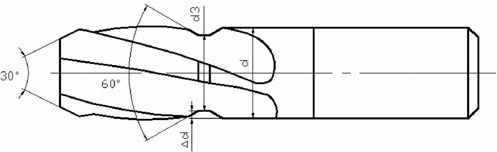
[0047] 1. Turning forming: Turning the alloy steel with a hard alloy inner diameter turning tool to obtain an alloy steel with an inner diameter of 52.8mm to 53mm, and then using a hard alloy outer diameter turning tool to turn the outer surface of the alloy steel with an inner diameter of 52.8mm to 53mm diameter, to obtain alloy steel pipes with an inner diameter of 52.8mm to 53mm and an outer diameter of 67.2mm to 67.4mm, and then use a carbide end face turning tool to turn the alloy steel pipe with an inner diameter of 52.8mm to 53mm and an outer diameter of 67.2mm to 67.4mm The end face is cut off with a cutting knife to obtain an alloy steel cage with a formed wide band size of 16.3mm to 16.5mm;

[0048] 2. Quenching and tempering treatment: perform quenching and tempering ...

specific Embodiment approach 2

[0079] Embodiment 2: This embodiment is different from Embodiment 1 in that: the cutting speed in step 1 is 120m / min-260m / min, and the feed rate is 0.2mm / r-0.25mm / r. Other steps and parameters are the same as those in the first embodiment.

specific Embodiment approach 3

[0080] Specific Embodiment 3: The difference between this embodiment and specific embodiment 1 or 2 is that the quenching and tempering treatment process described in step 2 is: cleaning first, and then quenching in a vacuum oil quenching furnace at a temperature of 835°C Treat for 40min to 45min, clean after quenching, and then temper in a vacuum tempering furnace at a temperature of 580°C for 120min to 130min to obtain a quenched and tempered alloy steel cage. Other steps and parameters are the same as those in Embodiment 1 or 2.


PUM

PropertyMeasurementUnit
The inside diameter ofaaaaaaaaaa
Outer diameteraaaaaaaaaa

Abstract

The invention provides a method for machining a circular hole alloy steel cage with inner-and-outer double fore shafts, relates to a method for machining a bearing cage and aims at solving the problems that the surface roughness of a cage pocket is unqualified, the wear rate of a drill bit and a milling cutter is high, the machining precision of the cage pocket is low, the sizes of the pocket and the inner-and-outer double fore shafts of the pocket are not stable, the inner-and-outer locking angles are difficult to guarantee, and the cage can not be installed in an outer casing when assembled and contact balls are prone to falling off. The method comprises the steps of forming by lathing, thermal refining, finish lathing for a first surface, finish lathing for a second surface, coarse grinding for outer circle, finish lathing for inner circle, uniform grinding for first surface and second surface, printing, lathing for inner step and inner groove, drilling, hole milling, lathing for outer step, finish uniform grinding for first surface and second surface, chamfer lathing, deburring, polishing, washing, final inspection and silver plating.

Description

technical field [0001] The invention relates to a processing method of a structural bearing cage. Background technique [0002] In order to improve the service life of aerospace bearings, three-point and four-point angular contact ball bearings are widely used in recent years. This kind of bearing has a strong bearing capacity and can bear bidirectional axial force. As one of the main components of the bearing, the cage has higher and higher requirements on its structure. In the assembly process, in order to prevent the bearing from falling apart, improve the reliability of the bearing during installation, and increase the service life of the bearing, the cage adopts a new structure with inner and outer double locks. [0003] However, the conventional technological process of the inner and outer double lock cages is: turning forming → quenching and tempering treatment → fine turning upper end surface → fine turning lower end surface → rough grinding outer circle → fine turn...

Claims


Application Information

Patent Timeline
IPC IPC(8): B23P15/00
CPCB23P15/003
Inventor 曹阳王大勇李迎丽薛雪王喆胡北关云朋刘伟王涛刘海波范继承高强朱磊李亚孙奇韩亭鹤高阳韩东海
Owner AVIC HARBIN BEARING
Why Eureka
Try Eureka