PM2.5 (Particulate Matter 2.5) source analyzing and sampling device based on carbon dioxide concentration control

A carbon dioxide, sampling device technology, applied in the sampling device and other directions, can solve the problems of inability to accurately control the dilution ratio, single flue gas sampling method, etc., and achieve the effects of easy promotion, reduced manufacturing difficulty, and guaranteed dilution ratio.

Inactive Publication Date: 2015-06-24
NANJING ASSEN ENVIRONMENT TECH
View PDF9 Cites 7 Cited by
  • Summary
  • Abstract
  • Description
  • Claims
  • Application Information

AI Technical Summary

Problems solved by technology

[0006] Aiming at the problems existing in the prior art that the flue gas sampling method is single and the dilution ratio cannot be precisely controlled, thereby simulating the real state of particulate matter emitted from pollution sources in the atmosphere, the present invention provides a PM2.5 source analysis sampling based on carbon dioxide concentration control device, which enables accurate sampling and simulation of particle aging

Method used


Image

  • PM2.5 (Particulate Matter 2.5) source analyzing and sampling device based on carbon dioxide concentration control

Examples


Embodiment 1

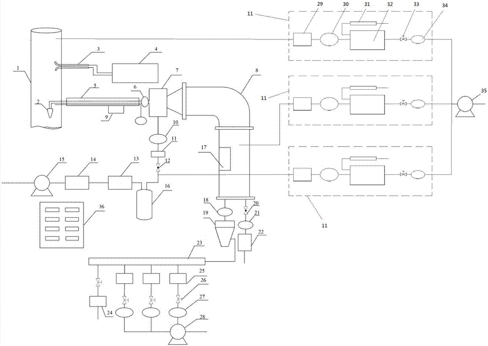
[0026] Such as figure 1 As shown, the PM2.5 source apportionment sampling device based on carbon dioxide concentration control in this embodiment includes a flue gas collection component, a mixing and dwelling chamber, a PM cutter 19, and a sampling and analysis unit.

[0027] The flue gas collection component is a unit for collecting flue gas, which is directly installed in the pipeline of the pollution source to collect the flue gas in the pipeline; the mixing and dwelling chamber is the area where the flue gas and the dilution gas are mixed and lodged, specifically including the dilution tank 7 and the dwelling chamber 8. The dilution tank 7 and the residence chamber 8 are connected to each other, the flue gas collection component is connected to the dilution tank 7, and the residence chamber 8 is connected to the sampling and analysis unit through the PM cutter 19.

[0028] In this embodiment, a second flowmeter 6 and an air delivery unit are also included. The second flo...

Embodiment 2

[0032] As a further solution of Embodiment 1, in this embodiment, the carbon dioxide detection unit 11 is composed of an acid desiccant 29, a high-efficiency particulate filter 30, a calibration device 31, a CO 2 Analyzer 32, ball valve 33, mass flow meter 34, CO 2 The analyzer 32 is provided with two inlets, and the acid desiccant 29 is connected to the CO through a high-efficiency particulate filter 30. 2 The inlet position of the analyzer 32, the calibration device 31 is connected to the CO 2 Another inlet position of the analyzer 32 for feeding CO 2 Analyzer Calibration, CO 2 The outlet of the analyzer 32 is connected to a mass flow meter 34 through a ball valve 33 , and the mass flow meter 34 is connected to a detection gas pump 35 . Such as figure 1 As shown, it is to detect the CO of the flue gas collection component, air delivery unit, and mixing residence 2 Concentration, in this embodiment, the connection positions of the three carbon dioxide detection units 11...

Embodiment 3

[0034] As a further solution of Embodiment 1, in this embodiment, a third flow meter 18, an emptying pipeline and a fourth flow meter 21 are also provided, and the third flow meter 18 is provided and connected to the residence chamber 8 and the PM cutter 19 Between them, the emptying pipeline is led out from the dwelling chamber 8, and is connected to the second proportional valve 20, the fourth flow meter 21 and the particulate matter filter 22 in sequence, and then is emptied.

[0035] In this embodiment, the third flowmeter 18 and the fourth flowmeter 21 are set to accurately monitor the gas volume at the outlet of the dwelling chamber 8. Since the PM in the flue gas has aging problems in the air, the sampling process will be based on different Sampling requirements require different precise flow control. Once the flow rate entering the residence chamber 8 is greater than the sampling flow rate, the pressure of the residence chamber 8 will increase, resulting in an increase ...


PUM


Abstract

The invention relates to the field of environmental monitoring equipment and particularly relates to a PM2.5 (Particulate Matter 2.5) source analyzing and sampling device based on carbon dioxide concentration control. The PM2.5 source analyzing and sampling device comprises a flue gas collecting assembly, a mixing residence chamber, a PM cutter and a sampling analysis unit, wherein the flue gas collecting assembly is connected to the mixing residence chamber, and the mixing residence chamber is connected to the sampling analysis unit through the PM cutter. The PM2.5 source analyzing and sampling device further comprises a second flowmeter, an air conveying unit, three carbon dioxide detecting units and a detecting air pump, wherein the flue gas collecting assembly, the air conveying unit and the mixing residence chamber are respectively connected to the carbon dioxide detecting units and then are connected to the detecting air pump. According to the PM2.5 source analyzing and sampling device, the traditional stationary pollution source sampling manner is adopted, the existing products can be subjected to improvement processing, the difficulty of manufacturing is lowered, the cost is relatively low, and thus, popularization is facilitated.

Description

technical field [0001] The invention relates to the field of environmental monitoring equipment, and relates to a sampling system for particulate matter emitted by fixed combustion sources, in particular to special equipment for collecting PM2.5. Background technique [0002] PM2.5 is a kind of fine particulate matter that can be inhaled in the lungs, its diameter is less than 2.5 microns, and it accounts for about 80% of the inhalable particulate matter PM10. However, during the combustion of fossil fuels, a large amount of particulate matter will be produced, which will be directly discharged into the air, which will endanger human health, cause air pollution and damage the ecological environment, especially PM2. The health and atmospheric environment have a greater impact. The existing technology mainly focuses on the dust removal of PM2.5 fine particles. There is no clear test data on the actual application effect. This involves the sampling and analysis of PM2.5 from fi...

Claims


Application Information

Patent Timeline
Patent Type & Authority Applications(China)
IPC IPC(8): G01N1/24
Inventor 刘德允陈莹彭先德贺磊梁宵王思敏
Owner NANJING ASSEN ENVIRONMENT TECH
Why Eureka
Try Eureka