
Container unit

A container and engine technology, applied in packaging, packaging food, assembly machines, etc., can solve problems such as impracticability, engine length and size limitations

Active Publication Date: 2015-06-24
MITSUBISHI HEAVY IND ENGINE & TURBOCHARGER LTD
View PDF5 Cites 3 Cited by
  • Summary
  • Abstract
  • Description
  • Claims
  • Application Information

AI Technical Summary

Problems solved by technology

[0006] However, the size of the container carried by ships, trucks, etc. is generally standardized, and the size is based on the specifications defined in the ISO standard. The length of the container is only 20f (6m) and 40f (12m). Containers are also standardized, but in Japan, under the current road traffic law, it does not work
), in addition, the width of the container is 8f (2.4m), and the height is 8.6f (2.6m). Therefore, there are only two types of containers that can be transported on public roads in Japan: 40f (12m) and 20f , the length and size of the engine that the container can accommodate is also of course limited

Method used


Image

  • Container unit
  • Container unit
  • Container unit

Examples


Embodiment Construction

[0080] Hereinafter, preferred embodiments of the present invention will be described in detail with reference to the accompanying drawings. However, unless otherwise specified, the dimensions, shapes, and relative arrangements of the components described in the examples are not intended to limit the scope of the invention, and are merely illustrative examples.

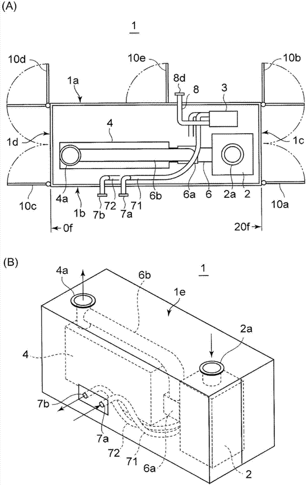
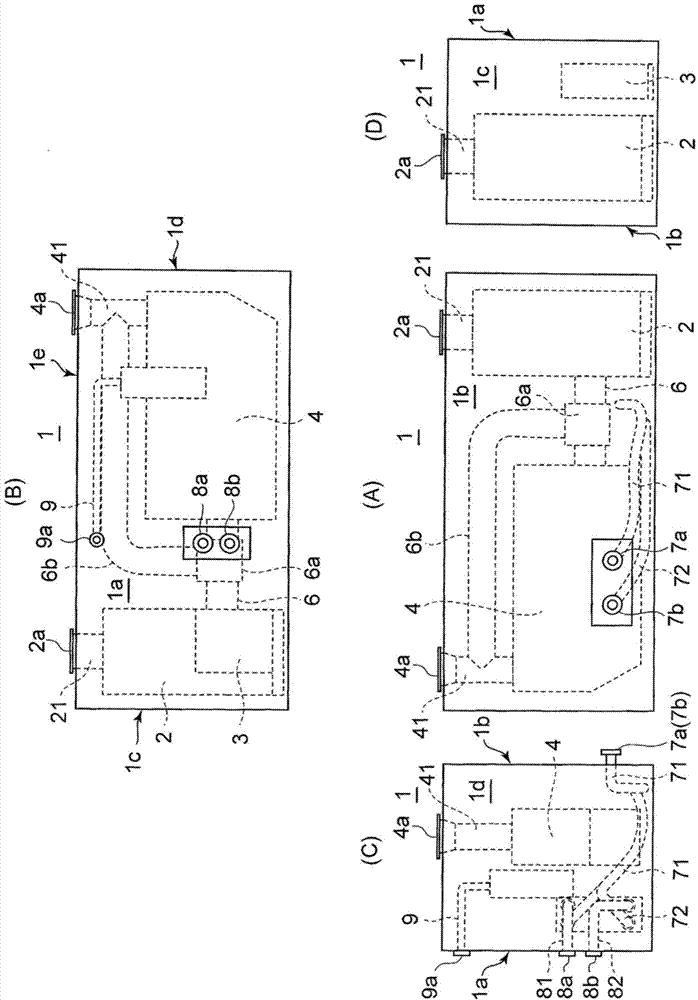
[0081] First, refer to figure 1 with figure 2 , in the embodiment of the present invention, the short utilization heat removal container (cogeneration container) will be described.

[0082] The heat exhausting container 1 is rectangular, and according to the ISO standard, its size is standardized as follows: container length 20f (6m), container width 8f (2.4m), height 8.6f (2.6m).

[0083] In this size pair utilizing heat rejection container 1, according to figure 1 (A), each of the walls on the four sides is defined separately: the long side wall located on the upper and lower sides of the figure is called the f...


PUM


Abstract

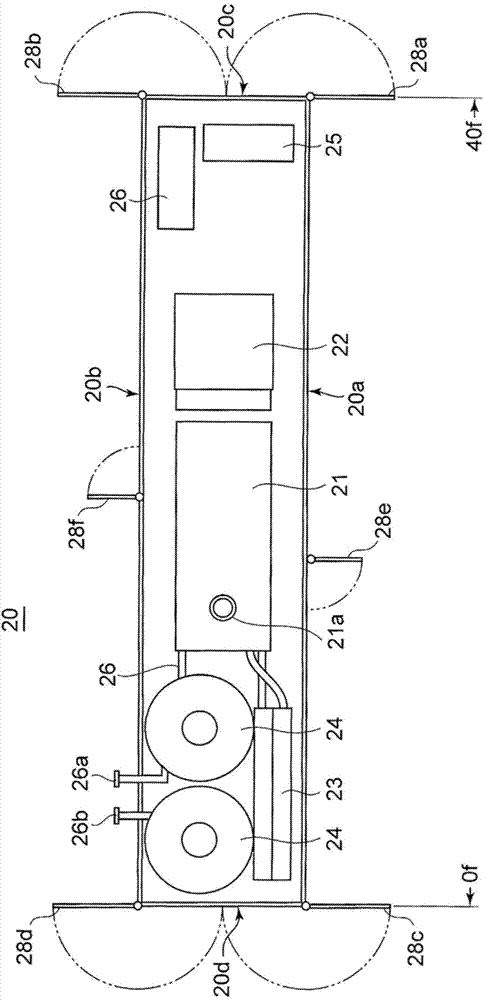
[Problem] To achieve an engine generator device in which effective utilization of containers is achieved by housing a generator functional unit, which itself houses an engine and a generator driven by said engine, in a longer generator container, and housing, in a shorter waste heat utilizing container, a heat converter and a boiler utilizing the heat discharged by the engine, wherein the two containers are effectively linked without the need for routing pipes or cables, which also saves space and makes for excellent maintainability even after assembly. [Solution] This container unit consists of a combination of: a longer generator container (20) which comprises a water-cooled engine (21) arranged in approximately the central position in the longitudinal direction of the container, and, on either side of the engine (21), a radiator (4) arranged on the 0f side of the container and a generator (22) arranged on the 40f side of the container, and which is provided with an engine exhaust gas outlet (21a) in approximately the central portion of the container directly above said engine; and a shorter waste heat utilizing container (1) comprising a muffler (2) arranged upright on the 20f side of the container, with an exhaust gas inlet (2a) in the top wall of the container, and comprising a boiler (4) which is disposed inside of the container space further towards the 0f side of the container than where the muffler stands upright and which generates steam by taking in exhaust gas of the engine (21) through the muffler (2). The longer generator container (20) and the shorter waste heat utilizing container (1) configure a combination unit in which longitudinal walls face one another and are aligned in parallel in the longitudinal direction, and the radiator (4) is arranged adjacent to the wall opposite of the wall facing the shorter waste heat utilizing container (1) and extends along said opposite wall.

Description

technical field [0001] The present invention relates to a container unit equipped with an engine power generation device using cogeneration, and more specifically, to a container unit that accommodates components on the generator body side including an engine and a generator driven by the engine. The container for power generation is combined with the waste heat utilization container which accommodates waste heat utilization equipment including boilers and heat exchangers for generating steam and hot water for hot water supply using the exhaust heat of the above-mentioned engine. Background technique [0002] Conventionally, an engine generator equipped with an engine and a generator driven by the engine is well known, because such an engine generator can be easily installed in response to a shortage of steady-state commercial power sources or an increase in power load in developing countries. , In addition, since the engine power generation device does not need a transmissi...

Claims


Application Information

Patent Timeline
Patent Type & Authority Applications(China)
IPC IPC(8): F02G5/02
CPCF02B63/044F02G5/02Y02E20/14Y02T10/12B65D85/68B65D2585/6877
Inventor 山中智和平井琢哉下平秀一成田浩一阿部猛
Owner MITSUBISHI HEAVY IND ENGINE & TURBOCHARGER LTD
Learn More