Vertical tube denitrification filler device

A technology of denitrification and standpipe, which is applied in the direction of granular microbial carrier treatment, water/sludge/sewage treatment, biological water/sewage treatment, etc. It can solve the difficulties of installation and replacement, easy rupture of aeration pipe, oxygen utilization rate, The actual service area is small and other problems, so as to achieve the effect of easy maintenance and installation, stable and reliable performance, and reduced power consumption when starting up

Inactive Publication Date: 2015-07-01
JIANGSU BOKAI ENVIRONMENTAL SCI & TECH
View PDF9 Cites 3 Cited by
  • Summary
  • Abstract
  • Description
  • Claims
  • Application Information

AI Technical Summary

Problems solved by technology

The current aeration devices are arranged horizontally at the bottom of the pool, which has disadvantages such as difficulty in installation and replacement, small actual service area, easy rupture of aeration tubes, and low oxygen utilization rate. Develop a high-efficiency denitrification packing standpipe aeration device with independent intellectual property rights is of great significance

Method used


Image

  • Vertical tube denitrification filler device
  • Vertical tube denitrification filler device
  • Vertical tube denitrification filler device

Examples


Embodiment 1

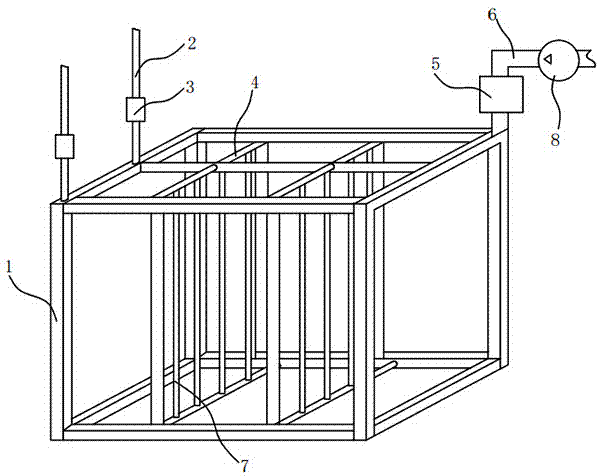
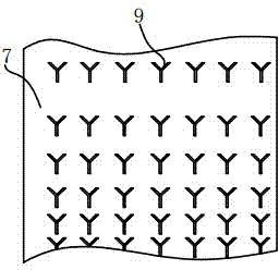
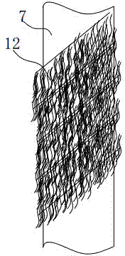
[0027] Embodiment 1: In the figure, said a kind of standpipe denitrification filling device includes a main pipe frame 1, a closed-circuit frame branch pipe 4 communicated with the main pipe frame 1, and a closed-circuit frame branch pipe 4 communicated with the closed-circuit frame branch pipe 4. The vertical aeration pipe 7, the air intake pipe 6 communicated with the main pipeline frame 1, the supply fan 8 communicated with the air intake pipe 6, the exhaust pipe 2 communicated with the main pipeline frame 1, are arranged on the The exhaust valve 3 on the exhaust pipe 2 and the air intake valve 5 arranged on the air intake pipe 6; the main pipeline frame 1 is formed by plugging PVC pipes or glass steel pipes, and the surface of the vertical aeration pipe 7 An aeration hole 9 is provided, and the vertical aeration pipe 7 is a pipe made of TPU or EMDP material; a denitrification filler 12 is woven around the periphery of the vertical aeration pipe 7, and the outer diameter of ...

Embodiment 2

[0034] Embodiment 2: The difference between this embodiment and Embodiment 1 is that the denitrification filler 12 is composed of a nylon mesh 10 and a fiber 11 wound on the nylon mesh 10 at one end, and the denitrification filler 12 is stacked. Wrapped around the vertical aeration pipe 7, the service life is long and the installation is simple.

[0035] Preferably, the diameter of the nylon fibers 11 of the nylon mesh 10 is 0.1-3 mm.

[0036] Preferably, the mesh diameter of the nylon mesh 10 is larger than the length of the fibers 11, so as to form a good anoxic layer and anaerobic layer.

Embodiment 3

[0037] Embodiment 3: The difference between this embodiment and Embodiment 1 is that the denitrification filler 12 is composed of a nylon intermediate rope 13 and a fiber 11 connected to the nylon intermediate rope 13 at one end, and the denitrification filler 12 is spirally wound on Around the vertical aeration tube 7, there is a gap 15 between two adjacent denitrification fillers 12, and the winding density of the denitrification filler 12 is positively related to the distance from the aeration tube, so that the aerobic layer, anoxic layer and anaerobic layer Smooth transition, better denitrification effect, low resistance loss.


PUM

PropertyMeasurementUnit
diameteraaaaaaaaaa

Abstract

The invention relates to a vertical tube denitrification filler device. The vertical tube denitrification filler device comprises a main pipeline frame, a closed circuit frame branch pipeline, a vertical aerator pipe, an air inlet pipe, an air supplier, an exhaust pipe, an air evacuation valve and an air inlet valve, wherein an aeration hole is formed in the surface of the vertical aerator pipe; denitrification filler is woven at the periphery of the vertical aerator pipe, outer diameter of the denitrification filler is 30-100mm, and the denitrification filler is made from fibers and completely covers the surface of the aerator pipe. The vertical tube denitrification filler device has the advantages that denitrification filler is directly arranged at the periphery of the vertical aerator pipe, the closed circuit frame branch pipeline is taken as an air circulating branch circuit, and oxygen utilization rate is high; the vertical tube denitrification filler device has a complete aeration functional module unit, maintenance and mounting are facilitated, performance is stable and reliable, and continuous or interrupted operation can be realized; the vertical aerator pipe is high in strength, resistant to corrosion and long in life, the aeration hole realizes self-closing function at water pressure, online cleaning can be carried out, blockage is prevented, and starting-up energy consumption is reduced; and denitrification filler can realize sludge reduction, and compared with the traditional activated sludge process, reduction amount of the residual activated sludge can be more than or equal to 50%.

Description

technical field [0001] The invention relates to the technical field of sewage treatment, in particular to a vertical pipe denitrification filling device. Background technique [0002] Water is a precious resource for human survival. With the rapid development of the economy, due to the widespread use of nitrogen-containing organic compounds, nitrogen-containing inorganic fertilizers and nitrogen-containing heterocyclic pesticides, a large number of complex nitrogen-containing pollutants will enter the water body, and the discharge of eutrophic substances will increase rapidly. increase. The eutrophication pollution of water body has caused great harm to the living environment of human beings. The ecological environment of water body is deteriorating day by day, which not only affects the normal life of human beings, but also restricts economic development, and causes huge direct and indirect economic losses to people. Therefore, the remediation of water polluted by eut...

Claims


Application Information

Patent Timeline
Patent Type & Authority Applications(China)
IPC IPC(8): C02F3/30
CPCC02F3/301C02F2003/001
Inventor 刘景明
Owner JIANGSU BOKAI ENVIRONMENTAL SCI & TECH
Why Eureka
Try Eureka