Direct connection type testing device for low-power-consumption differential transmission chip

A differential transmission and test device technology, applied in the field of direct test devices for low-power differential transmission chips, can solve the problems of difficulty in developing test programs, narrow use range, time-consuming and labor-intensive problems, and achieve good portability and low procurement costs , the effect of convenient use

Active Publication Date: 2015-07-01
CHINA ELECTRONIC TECH GRP CORP NO 38 RES INST
View PDF7 Cites 2 Cited by
  • Summary
  • Abstract
  • Description
  • Claims
  • Application Information

AI Technical Summary

Problems solved by technology

However, most existing devices for testing differential transmission rely on the entire system. By designing FPGA test logic, connecting corresponding chips one by one through LVDS (Low Voltage Differential Signaling) cables, and then checking chip failures with an oscilloscope, this This method is not only time-consuming and labor-intensive, but also has a very narrow scope of use
In addition, with the development of equipment and electronic technology, the types of interfaces are constantly being upgraded and improved, so the method of simply designing FPGA test logic cannot well solve the general problem of low-power differential transmission chip testing
Finally, the complex wiring interface and hardware wiring mode will also make it difficult to develop test programs, which will affect the use of

Method used


Image

  • Direct connection type testing device for low-power-consumption differential transmission chip
  • Direct connection type testing device for low-power-consumption differential transmission chip
  • Direct connection type testing device for low-power-consumption differential transmission chip

Examples


Embodiment Construction

[0017] In order to make the object, technical solution and advantages of the present invention more clear, the present invention will be further described in detail below in conjunction with the accompanying drawings and embodiments. It should be understood that the specific embodiments described here are only for explaining the present invention, and are not intended to limit the present invention.

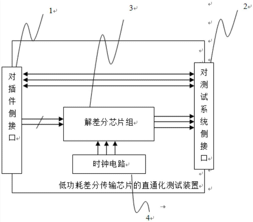
[0018] refer to figure 1 , a test device for a low-power differential transmission chip, including a plug-in side interface 1, a test system side interface 2, a differential chip set 3 and a clock circuit 4, wherein the plug-in side interface 1 and the test system side interface 2 pass Direct one-to-one connection and two-way communication through parallel lines; the differential solution chip set 3 is connected to the interface 1 on the plug-in side through differential lines and communicates in one direction, and communicates with the interface 2 on the test system side through...


PUM


Abstract

The invention discloses a direct connection type testing device for a low-power-consumption differential transmission chip. The direct connection type testing device comprises an insert side interface, a testing system side interface, a difference solution chip group and a clock circuit. The insert side interface is directly in one-to-one connection and in two-way communication with the testing system side interface through parallel wiring. The difference solution chip group is in one-to-one connection and in one-way communication with the insert side interface through differential wiring, and is in one-to-one connection and in one-way communication with the testing system side interface through parallel wiring. The clock circuit is connected with the difference solution chip group. The direct connection type testing device has the advantages that the device is simple in structure and compact in wiring; mature chips and electronic components are adopted, and low purchase cost and high portability are achieved.

Description

technical field [0001] The invention relates to the field of circuit testing, in particular to a through testing device for low power consumption differential transmission chips. Background technique [0002] Electronic devices widely used in the industrial field are becoming more automated and intelligent, but due to the large number of low-power differential transmission chips, such as DS90CR285 and DS90CR286 chips, it is difficult to locate these electronic devices when there is a transmission failure If the fault point, especially the short circuit of the fine-pitch pins, cannot be found by naked eyes, it can only be solved by replacing a new chip, which will increase the debugging cost and reduce the reliability of the circuit board. [0003] In such cases, it is important to be able to accurately test low-power differential transmission chips. However, most existing devices for testing differential transmission rely on the entire system. By designing FPGA test logic, ...

Claims


Application Information

Patent Timeline
Patent Type & Authority Applications(China)
IPC IPC(8): G01R31/28
Inventor 刘静曹俊锋柏光东王凤驰李正东
Owner CHINA ELECTRONIC TECH GRP CORP NO 38 RES INST
Why Eureka
Try Eureka