
Resonator for lithography equipment noise reduction

A technology of lithography equipment and resonator, which is applied in microlithography exposure equipment, photolithography process exposure devices, etc., can solve the problems of huge influence on the internal world of the lithography machine.

Active Publication Date: 2015-07-01
SHANGHAI MICRO ELECTRONICS EQUIP (GRP) CO LTD
View PDF7 Cites 2 Cited by
  • Summary
  • Abstract
  • Description
  • Claims
  • Application Information

AI Technical Summary

Problems solved by technology

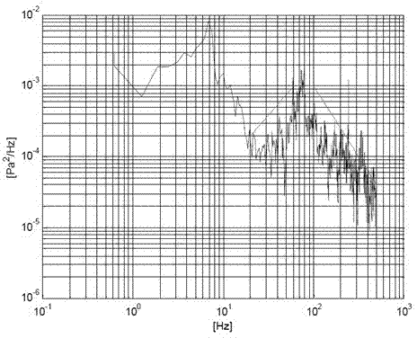
[0012] The defect in the above-mentioned technical solution for noise elimination is that reverberation noise also has a huge impact on the internal world of the lithography machine, and there is no solution for this in the existing technical solution

Method used


Image

  • Resonator for lithography equipment noise reduction
  • Resonator for lithography equipment noise reduction
  • Resonator for lithography equipment noise reduction

Examples


Embodiment Construction

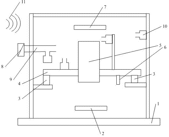
[0026] A resonator for lithography equipment according to a specific embodiment of the present invention will be described in detail below with reference to the accompanying drawings. However, the present invention should be understood as not limited to such embodiments described below, and the technical idea of ​​the present invention can be implemented in combination with other known technologies or other technologies having the same functions as those known technologies.

[0027]In the following description, in order to clearly show the structure and working method of the present invention, many directional words will be used to describe, but "front", "rear", "left", "right", "outer", "inner" should be used Words such as ", "outward", "inward", "upper" and "lower" are to be understood as convenient terms, and should not be understood as restrictive terms. In addition, the term "X direction" used in the following description mainly refers to the direction parallel to the hor...


PUM


Abstract

The invention discloses a resonator for lithography equipment noise reduction. The resonator includes: an inner cavity and a pipe orifice connected to the inner cavity. The pipe orifice consists of an outer wall, an air layer, a sound absorption layer and an inner wall perforated plate from the outside in sequentially. The resonator provided by the invention can realize adjustable resonant frequency, and makes the resonant frequency similar to that of a noise source, thus reaching the technical effect of effective sound absorption.

Description

technical field [0001] The invention relates to the field of integrated circuit equipment manufacturing, in particular to a resonator used for noise reduction of lithography equipment. Background technique [0002] A lithographic apparatus is a machine that applies a desired pattern to a substrate. For example, lithographic equipment may be used in the manufacture of integrated circuits (ICs). In this case, a patterning device, alternatively referred to as a mask or reticle, may be used to generate a circuit pattern corresponding to a single layer of the IC. The pattern can be imaged onto a target portion (eg, comprising a portion, one or more dies) on a substrate (eg, a silicon wafer). Pattern imaging is performed by imaging the pattern onto a layer of radiation sensitive material (resist) provided on the substrate. Typically, a single substrate will contain a network of adjacent target portions that are sequentially exposed. A conventional lithographic apparatus compri...

Claims


Application Information

Patent Timeline
Patent Type & Authority Applications(China)
IPC IPC(8): G03F7/20
Inventor 胡月钟亮王璟
Owner SHANGHAI MICRO ELECTRONICS EQUIP (GRP) CO LTD
Learn More