De-soldering method for elements with bottom terminal packaging

A component and terminal technology, applied in the field of desoldering, can solve problems such as inability to remove solder components, increase high temperature resistance, and insufficient heating time, and achieve direct and rapid heat transfer, less heat loss, and short heat action time Effect

Inactive Publication Date: 2015-07-08
CHENGDU KAITIAN ELECTRONICS
View PDF6 Cites 2 Cited by
  • Summary
  • Abstract
  • Description
  • Claims
  • Application Information

AI Technical Summary

Problems solved by technology

This method will undoubtedly increase the risk of high temperature resistance of the component body (1). If the temperature of the hot air is too high or the time for blowing hot air is too long, the component body (1) will be burned or cause internal damage, and the component body ( 1) The lower printed board (6) is scalded; the temperature of the hot air is low or the heating time is insufficient, and the components in the unmelted state of the solder cannot be removed, or in the process of removing the components by external force in the semi-melted state, tearing The pads (7) used to connect the bottom surface terminals (4) of the component body (1) on the printed circuit board

Method used


Image

  • De-soldering method for elements with bottom terminal packaging
  • De-soldering method for elements with bottom terminal packaging

Examples


Embodiment Construction

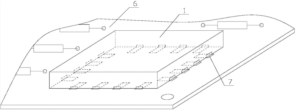
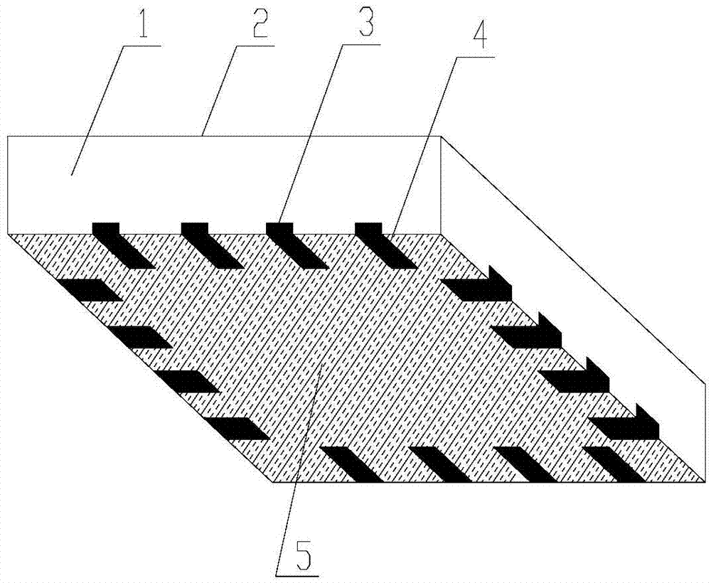
[0012] refer to figure 1 , figure 2 . According to the desoldering method of packaged components with bottom terminals of the present invention, a silver-plated copper wire with a diameter and length suitable for the invention recommendation Φ0.08mm, which can be wound around the component body for two weeks, is used to wrap around the component body 1 and The joint part of the printed board 6 is two weeks, and the silver-plated copper wire is required to be in close contact with the solder joint and the metal part connected to the solder joint, and the silver-plated copper wire should be close to: the junction of the component body 1 and the printed board pad 7 Invention at the solder joints at the bottom, the exposed part of the solder pad after the printed board 6 is assembled with components is extremely small, the exposed terminal side part 3 of the bottom terminal 4 of the component body 1; the length Φ0 can be wrapped around the component body for about two weeks .08...


PUM

PropertyMeasurementUnit
diameteraaaaaaaaaa

Abstract

The invention discloses a de-soldering method for elements with bottom terminal packaging and aims at providing a de-soldering method which is short in operation time and capable of not burning elements and printed boards. According to the technical scheme, a silver plated copper wire with the diameter phi in a range of 0.08mm to 0.12mm is used for winding the element body (1) and printed circuit board (6) joint portion for two circles, and the length of the silver plated copper wire is that the silver plated copper wire can wind the element body for at least two circles. The silver plated copper wire is attached to the soldering disc exposure portions of the element body (1) and printed circuit board soldering pad (7) bottom soldering point connection positions and exposed terminal side portions (3) of bottom terminals (4) of the element body (1) to wound all soldering points; the exposed silver plated copper wire is heated directly through electric soldering iron, a certain amount of soldering flux is added at the position of a soldering tip while the silver plated copper wire is heated, heat is transmitted to the bottom terminals and the printed circuit board soldering disc through the silver plated copper wire and the exposed fused soldering flux directly, and all heat is concentrated to the soldering points rapidly, accordingly, the apparatus is taken down.

Description

technical field [0001] The invention relates to a desoldering method capable of protecting printed boards and components from large-area high-temperature burns, cracks, and other packaged components with bottom terminals. Background technique [0002] In the prior art, after the components packaged with the bottom terminals are soldered on the printed board, the components need to be removed after desoldering due to reasons such as weak soldering and internal failure of the components. The traditional method is to protect the printed board from heat damage, and the method of destroying the component body is often used for brutal disassembly, which is not conducive to component failure analysis and problem finding. At present, the common desoldering of surface mount components is to blow hot air on the welding points of components through small hot air reflow special equipment, that is, through hot air heat transfer and component bodies (component bodies are mostly plastic or...

Claims


Application Information

Patent Timeline
Patent Type & Authority Applications(China)
IPC IPC(8): B23K1/018
CPCB23K1/018
Inventor 蔡成曾丽霞董洪杰李博陈茜张平华吴婉秋
Owner CHENGDU KAITIAN ELECTRONICS
Why Eureka
Try Eureka