Novel nano electrostatic frictional spinning device

A friction spinning, nano-scale technology, applied in the field of nano-scale electrostatic friction spinning devices, can solve the problems of low electrostatic spinning manufacturing efficiency, application field limitations, etc., to improve spinning efficiency, increase utilization rate, and expand application fields Effect

Active Publication Date: 2015-07-08
SHANGHAI UNIV OF ENG SCI
View PDF5 Cites 26 Cited by
  • Summary
  • Abstract
  • Description
  • Claims
  • Application Information

AI Technical Summary

Problems solved by technology

[0004] The technical problem to be solved by the present invention is that the manufacturing ...

Method used


Image

  • Novel nano electrostatic frictional spinning device
  • Novel nano electrostatic frictional spinning device
  • Novel nano electrostatic frictional spinning device

Examples


Embodiment 1

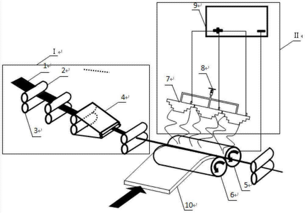
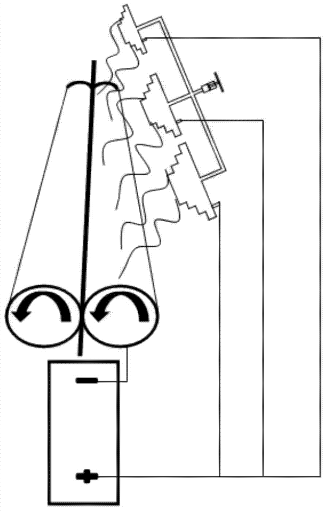
[0025] join Figure 1-Figure 2 , a new nano-scale electrostatic friction spinning device, including a drafting mechanism that sequentially drafts a fiber assembly 1, that is, four top rollers, two four rollers, three double aprons, and four rollers. Twist area, as the yarn core; the friction roller for twisting the yarn, one of which is made of metal solid material 5, and the other is made of non-metallic hollow material 6, which can rotate clockwise or counterclockwise at the same time; the metal solid friction roller is set above There is an electrospinning device for preparing nanofibers, including a pyramid-shaped spinneret 7, a barrel 8, and a voltage 9; the top of the friction roller is provided with an airflow tube 9 that can transport airflow, and squeezes the yarn in the wedge-shaped groove downward, At the same time, the non-metallic hollow friction roller pumps air to ensure that the core yarn and nanofiber can be absorbed in the wedge-shaped groove together; the fr...

Embodiment 2

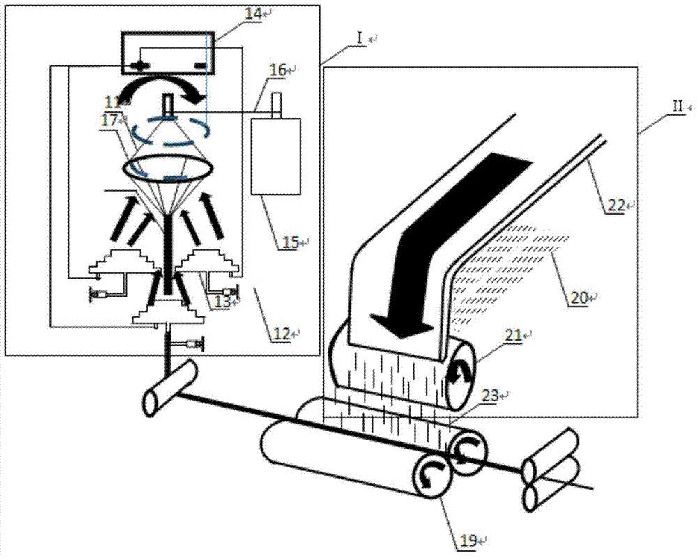
[0027] see Figure 3-Figure 4 , in the feeding zone I, an electrospinning nanofiber yarn device is set. The internal device in the section includes a horn-shaped receiver 11, a barrel 12, a pyramid-shaped spinneret 13, an electrostatic generator 14, a motor 15, and a chain 16; Electrostatic generator 14 negative pole, pyramid-shaped spinneret 13 is connected to electrostatic generator 14 positive pole, an electric field is formed between the positive and negative poles to stretch the nanofibers; a motor 15 rotating at a certain speed drives a horn-shaped receiver for collecting nanofibers 11. The horn-shaped receiver 11 rotates to form an air flow, and the nanofibers are helically deposited on the receiving ring 17 of the horn-shaped receiver 11 under the drive of the electric field force, and the deposited nanofibers are rotated and twisted under the drive of the airflow to form a nanofiber yarn 18, then introduce the friction stick 19 wedge-shaped bad. In the feeding zone ...

Embodiment 3

[0029] See Figure 4 and Figure 5 . In the feeding zone 1, traditional fibers are fed, and the cooked sliver is fed to the friction roller twisting zone along the axis through the four-roller double apron drafting device as the yarn core; in the feeding zone 2, the cooked sliver is fed and carded During the rolling process, a metal plate 24 is added between the cooked sliver and the air flow pipe, and a pyramid-shaped spinneret is added below the cooked sliver. The metal plate is connected to the negative pole, and the spinneret is connected to the positive pole. The charged nanofibers were stretched. But since the sliver is also in the middle of the electric field, the nanofibers are actually deposited under the sliver and eventually fed to the opening roller with the sliver. The metal plate is only used as an induction negative electrode to stretch the nanofiber, and is not used as a receiver. Therefore, in the feeding zone II, there are both non-nanoscale fibers and na...


PUM


Abstract

The invention relates to a novel nano electrostatic frictional spinning device. the device comprises a feeding area I, a feeding area II and a pair of frictional rollers, wherein the yarns in the feeding area I are conveyed in the axial direction of each frictional roller shaft; the yarns in the feeding area II are conveyed in the radial direction of each frictional roller shaft; the feeding area I and the feeding area II are respectively used for spinning and conveying of yarn fiber combination bodies and electrostatic nano fibers; the yarn fiber combination bodies and the electrostatic nano fibers are combined at the pair of frictional rollers rotating in the same direction; yarn strips are gyrated under the effect of gyring torque generated by the frictional rollers so as to form covering yarns with the nano fibers at the outside or inside, or form the covering yarns with the nano fibers and the yarn fiber combination bodies at the outside and the nano fibers at the inside; then the covering yarns are drawn out through a stretching roller. With the adoption of the device, the yarn structure is compact; the problems of leather and yarn evenness caused by the nano fibers can be avoided; the yarns are high in moisture absorbing performance, oil absorbing performance and filtering performance; the utilization rate of the electrostatic spun nano fibers can be increased, and the application field of an electrostatic spinning machine can be expanded.

Description

technical field [0001] The invention relates to a spinning device, in particular to a nano-level electrostatic friction spinning device, which belongs to the technical field of spinning. Background technique [0002] Friction spinning is a kind of open-end spinning, and its spinning principle is yarn made by friction and twisting. The traditional DII friction spinning device uses opening rollers to open the fibers into single fibers, and then sends the fibers to a pair of friction rollers rotating in the same direction with airflow through the pipeline, thereby producing twisted yarns. The DⅢ type friction spinning machine has two feeding units, one provides the yarn core, and the other supplies the outsourcing fiber, and the cooked sliver is fed into the dust cage twisting area along the axis through the four-roller double-apron drafting device as the yarn core; 4 -6 raw slivers are fed side by side into the drafting mechanism with three upper rollers and two lower rollers...

Claims


Application Information

Patent Timeline
IPC IPC(8): D01H4/16D01H4/28
Inventor 辛斌杰奚桐
Owner SHANGHAI UNIV OF ENG SCI
Why Eureka
Try Eureka