
Double-mouse-cage composite cage bar efficient motor rotor and manufacturing method thereof

A technology of composite cage bars and double squirrel cages, which is applied in the field of electric motors, can solve the problems of failure to achieve the qualified rate of aluminum casting, high overall cost of rotors, and poor versatility of parts, so as to improve starting performance and working performance and shorten production The effect of cycle, production and manufacturing convenience

Inactive Publication Date: 2015-07-08
江苏利得尔电机有限公司
View PDF0 Cites 11 Cited by
  • Summary
  • Abstract
  • Description
  • Claims
  • Application Information

AI Technical Summary

Problems solved by technology

[0002] At present, AC asynchronous motors are commonly used in electric machinery, and usually adopt squirrel cage rotor structure. The main disadvantage is that the starting characteristics are poor, and the efficiency improvement is limited under the condition of volume limitation.
In order to meet the energy efficiency requirements of IE3 and IE4 in the small and medium power range, the motor must increase the volume, increase the material, and the parts have poor versatility
[0003] Using the copper casting process, the biggest challenge for the copper casting rotor is the casting process problem, because the melting point of aluminum is 700 ° C, while the melting point of copper is as high as 1100 ° C, such a high temperature is a great test for the mold and silicon steel sheet, and the cost of the casting mold High, short life, unable to achieve the pass rate of casting molding like aluminum, resulting in too high overall cost of the rotor, it is difficult to popularize and apply at present

Method used


Image

  • Double-mouse-cage composite cage bar efficient motor rotor and manufacturing method thereof
  • Double-mouse-cage composite cage bar efficient motor rotor and manufacturing method thereof

Examples


Embodiment Construction

[0032] The present invention will be further described below in conjunction with the accompanying drawings and description of the accompanying drawings.

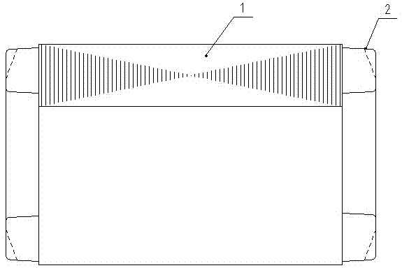
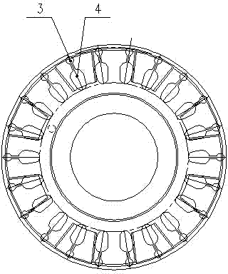
[0033] A high-efficiency motor rotor with double squirrel-cage composite cage bars, including the rotor, the iron core of the rotor includes inner and outer squirrel cages where the squirrel-cage bars are close to or tangent to each other, and the ends of the squirrel-cage bars at both ends of the inner and outer squirrel-cages The rings 2 are respectively connected as one; in order to improve the starting characteristics of the asynchronous motor, the outer cage bar 3 of the outer cage is made of aluminum casting material with high resistivity, and the inner cage bar 4 is pure copper (copper) rod with low resistivity , The section of the inner and outer squirrel cage bars in the iron core of the rotor is circular, oval, pear-shaped or knife-shaped. The total cross-section of the inner and outer cage bars of each cage corres...


PUM


Abstract

The invention relates to a double-mouse-cage composite cage bar efficient motor rotor and a manufacturing method thereof, and belongs to the technical field of motors. The double-mouse-cage composite cage bar efficient motor rotor comprises a rotor body, an iron core of the rotor body includes an inner mouse cage and an outer mouse cage with mouse cage bars being close to each other or tangent to each other, and end rings at the two ends of each mouse cage bar of the inner mouse cage and the outer mouse cage are connected into a whole; the outer mouse cage is made of a high electrical resistivity aluminum casting material, and the inner mouse cage is made of a low electrical resistivity pure copper (red copper) bar material. The manufacturing method of the composite cage bar efficient motor rotor includes the following steps that 1, the rotor iron cores are overlaid; 2, inner mouse cage pure copper (red copper) bars are arranged alternately; 3, aluminum casting is conducted on the outer mouse cage of the rotor. The device is reasonable and simple in structure, the manufacturing method is scientific and advanced, the first-pass yield of products is high, and the production cycle of the products is shortened.

Description

technical field [0001] The invention relates to a high-efficiency motor rotor with double squirrel cage composite cage bars and a preparation method thereof, belonging to the technical field of motors. Background technique [0002] At present, AC asynchronous motors are commonly used in electric machinery, and usually adopt squirrel-cage rotor structure. The main disadvantage is that the starting characteristics are poor, and the efficiency improvement is limited under the condition of volume limitation. In order to meet the energy efficiency requirements of IE3 and IE4 in the small and medium power range, it is necessary to increase the volume, increase the material, and the parts have poor versatility. [0003] Using the copper casting process, the biggest challenge for the copper casting rotor is the casting process problem, because the melting point of aluminum is 700 ° C, while the melting point of copper is as high as 1100 ° C, such a high temperature is a great test f...

Claims


Application Information

Patent Timeline
IPC IPC(8): H02K17/18H02K15/02
Inventor 开志宏李佳友王聪王军昌李扬周康林
Owner 江苏利得尔电机有限公司
Learn More