Ultra high voltage regulator

A voltage regulator, ultra-high voltage technology, applied in electrical components, output power conversion devices, DC power input conversion to DC power output and other directions, can solve problems such as driver chip damage

Active Publication Date: 2015-07-08
DIWIN TECH
View PDF6 Cites 2 Cited by
  • Summary
  • Abstract
  • Description
  • Claims
  • Application Information

AI Technical Summary

Problems solved by technology

When the LED in any light string is da...

Method used


Image

  • Ultra high voltage regulator
  • Ultra high voltage regulator
  • Ultra high voltage regulator

Examples


Embodiment Construction

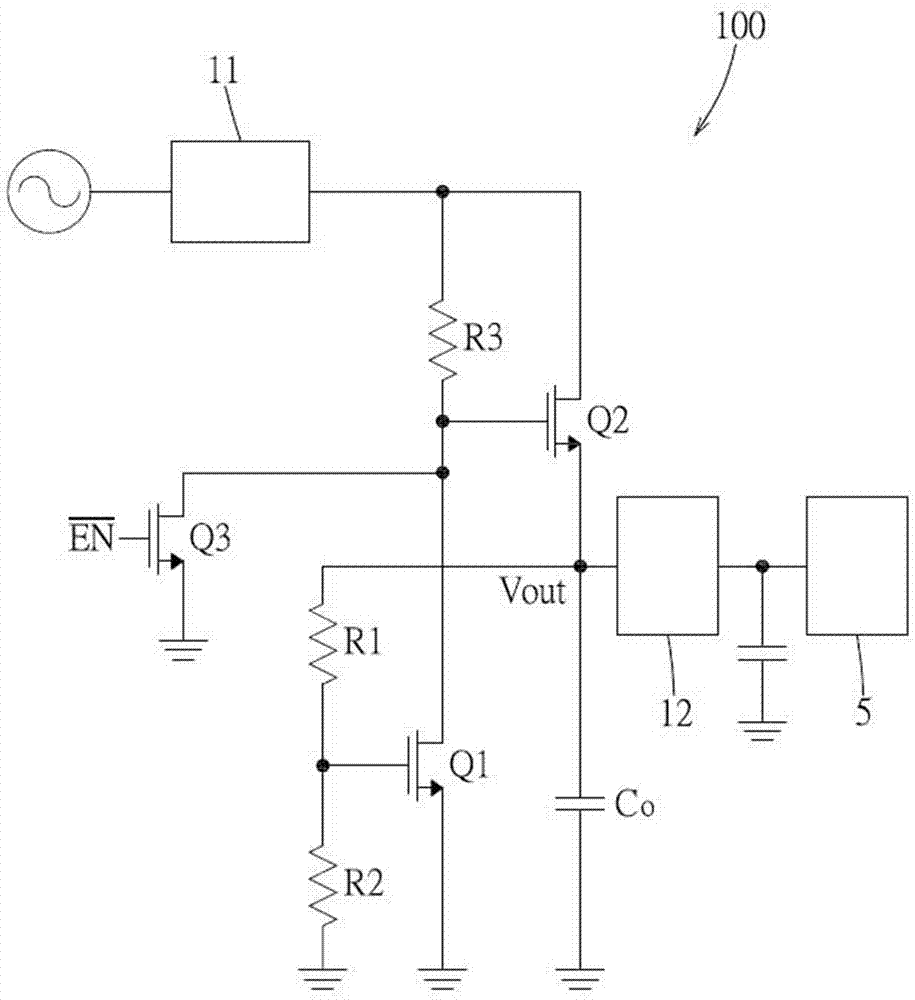
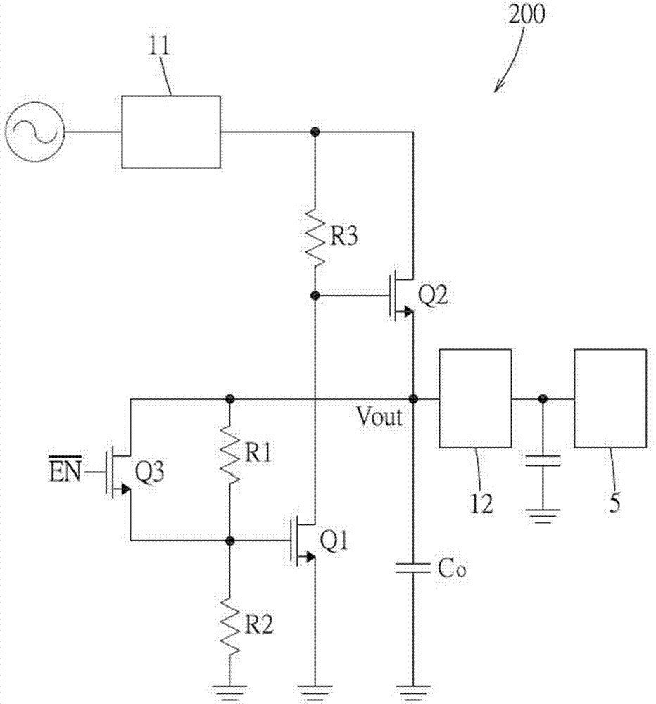
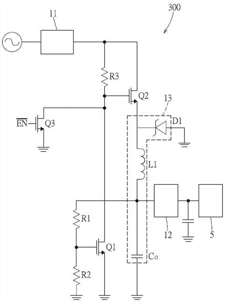
[0034] Before the present invention is described in detail, it should be noted that in the following description, similar components are denoted by the same numerals. In addition, the switch components mentioned below may be bipolar junction transistors (BJTs) or field effect transistors (MOSFETs). For convenience of description, each embodiment is described by taking a field effect transistor as an example.

[0035] refer to figure 1 , in the first embodiment of the present invention, the ultra-high voltage voltage regulator 100 has an input terminal receiving an alternating current (eg: 110 volts) of a commercial power supply and an output terminal, thereby generating a DC output voltage Vout through the output terminal . The extra-high voltage voltage regulator 100 also includes a DC-to-DC converter 12 (or a linear voltage regulator) to output a low voltage (such as: 5 volts or 3.3 volts) that meets the requirements of the electronic component 5 and supply it to the electr...


PUM


Abstract

An ultra high voltage regulator for converting includes a rectifying circuit, a first transistor, a second transistor, an output capacitor, a first resistor, a second resistor, and a third resistor. The ultra high voltage regulator converts a received alternative current into a direct voltage to an electrical component. The ultra high voltage regulator capable of providing a larger current becomes more compact and thinner in size without cooperating with a mass transformer/high voltage capacitor, which satisfies the request for miniaturization of the electrical components.

Description

technical field [0001] The invention relates to a voltage regulator, in particular to an ultra-high voltage voltage regulator which is applicable to large current, is not easy to generate heat, and does not need to use volume-occupied inductors / high-voltage capacitors. Background technique [0002] At present, common AC-to-DC power supply devices are divided into linear type and switching type. [0003] The linear power supply device requires a large-volume heat dissipation component in the case of high-voltage and high-current (tens of mA) input, and the conversion efficiency is extremely low. [0004] The conversion efficiency of the switching power supply device is better than that of the linear power supply device, which can be roughly divided into several circuits: non-isolated buck-boost circuit, isolated flyback (flyback) circuit, non-isolated buck circuit, Isolated forward circuits, and push-pull (push-pull) circuits; however, isolated circuits have the disadvantage...

Claims


Application Information

Patent Timeline
IPC IPC(8): H02M7/217
CPCH02M7/217H02M3/156
Inventor 徐景岳
Owner DIWIN TECH
Why Eureka
Try Eureka