Cervical posterior approach Y-shaped plate and manufacturing method thereof

A posterior approach, cervical spine technology, applied in the field of spinal internal fixation device and its preparation, can solve problems such as inability to be absorbed by tissue, mismatched mechanical properties, spinal cord injury, etc., achieve good biological activity and biocompatibility, and reduce surgical risks. , the effect of shortening the operation time

Active Publication Date: 2015-07-15
SICHUAN GUONA TECH
View PDF10 Cites 1 Cited by
  • Summary
  • Abstract
  • Description
  • Claims
  • Application Information

AI Technical Summary

Problems solved by technology

If the screws fixing the bone graft become loose or the bone graft cannot be ossified and fused with the lamina and lateral mass, the bone graft may fall into the spinal canal and cause spinal cord injury; in addition, because the lamina of the human cervical spine is thin, The micro-titanium plate is fixed on the lamina with screws. Due to the small fixation force, it is difficult to form a strong internal fixation
[0010] However, the spine fixation plate system proposed by CN201710448U has problems such as that the sliding hook fixed on the sliding groove to adjust the door opening is loose and loses the effective door opening, and the single length of the steel plate can easily cause the imbalance of the coronal plane of the spine. In addition, its mechanical properties do not match the human bone. , there are shortcomings such as stress shielding, foreign body sensation, inability to be absorbed by tissues, and electrolytic foreign body rejection, which will further cause some complications

Method used


Image

  • Cervical posterior approach Y-shaped plate and manufacturing method thereof
  • Cervical posterior approach Y-shaped plate and manufacturing method thereof

Examples


Embodiment 1

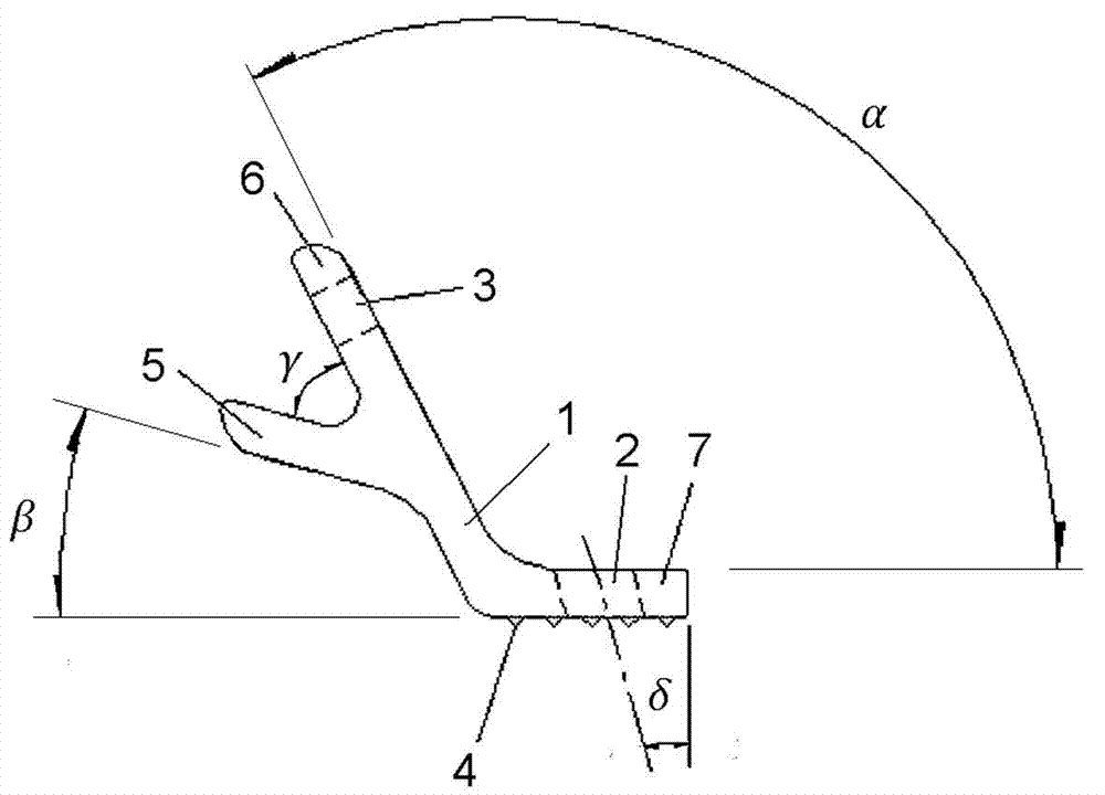
[0028] figure 1 Shown is a structural form of the cervical posterior Y-shaped plate of the present invention, which is made of nano-hydroxyapatite-medical polyamide 66 composite material. Its overall structure is a Y-shaped structure composed of two branch structures 5 and 6 forming the end of the V-shaped opening and a tail 7 extending from the V-shaped junction of the two branch structures. Through-holes 3 and 2 are respectively opened on one side branch structure 6 and the tail part 7 constituting the V-shaped structure. Wherein the through hole 2 of the tail part 7 has a slant hole of 5-30° between the axial direction of the hole and the extending direction of the tail part 7 . The diameter of the through hole on the branch structure 6 can generally be 1-5 mm; the diameter of the through hole on the tail 7 can generally be 2-5 mm. The width of the tail 7 in the cross-sectional direction of the through hole 2 can generally be adjusted within the range of 4-12mm according ...

Embodiment 2

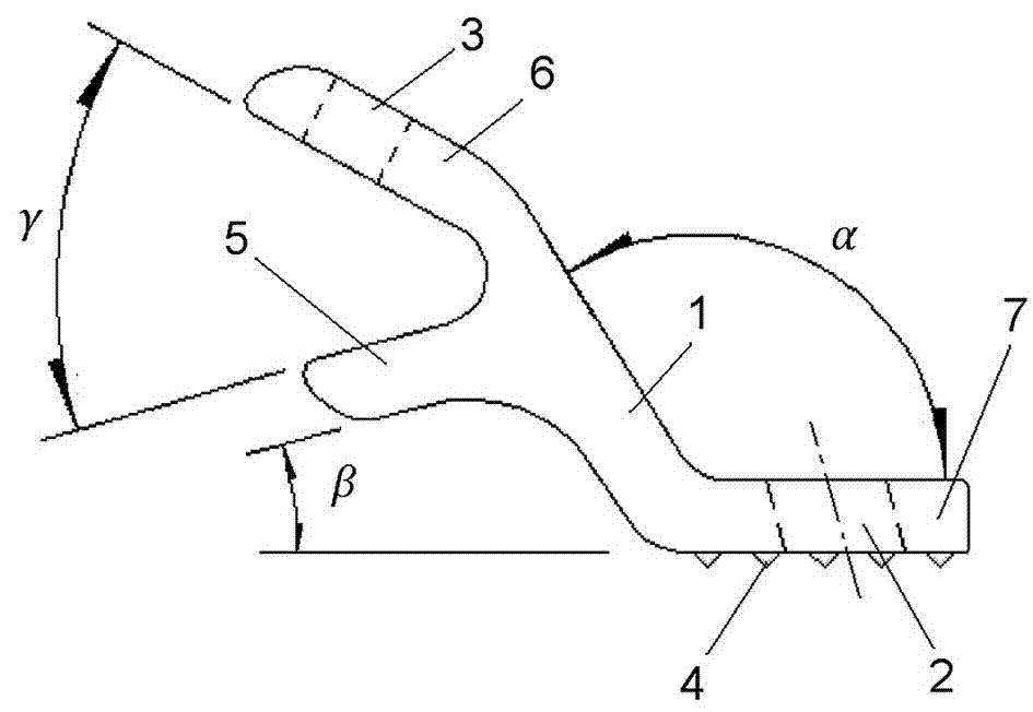
[0033] like figure 2 As shown, the structure of the posterior cervical Y-shaped plate in this case is consistent with that of figure 1 The main difference is that the angle β between the extension direction of the branch structure 5 without through holes and the extension direction of the tail 7 in the two branch structures with V-shaped openings at the ends is V-shaped between the two branch structures. Negative value form of 0~ -20° with opposite angle γ direction. The tail portion 7 is in the form of a continuous extension between the extension transition section 1 of the branch structure 6 with the through hole 3 and the turning continuation section with the said included angle α.

[0034] The basic process of the preparation method of the cervical posterior Y-shaped plate is consistent with that of Example 1, and the raw material is nano-hydroxyapatite-medical polyamide 6 (which can also be prepared by referring to the above-mentioned literature). According to the diff...


PUM


Abstract

The invention relates to a cervical posterior approach Y-shaped plate and a manufacturing method thereof. The cervical posterior approach Y-shaped plate is a Y-shaped structure body composed of ends with a V-shaped opening and a tail, wherein the ends with the V-shaped opening are formed by two branched structures, and a V-shaped combination part of the two branched structures extends to form the tail. Through holes are formed in the branched structure on one side and the tail, wherein an included angle ranging from 95 degrees to 140 degrees is formed between the extending direction of the branched structure with the through hole and the extending direction of the tail; and an included angle ranging from -20 degrees to 20 degrees is formed between the extending direction of the branched structure without the through hole and the extending direction of the tail. When the cervical posterior approach Y-shaped plate is manufactured, after a medical injection molding material is injected into a mold under the conditions of the injection molding temperature and pressure, cooling molding is carried out. The cervical posterior approach Y-shaped plate can have the performance like the mechanical strength and tenacity matched with the human bone, the good biological activity and the good biocompatibility; stress shielding can be effectively reduced; fusion of a postoperation product and tissues and supporting expansion on the canalis vertebralis can be facilitated; decompression of a re-closing operation can be effectively controlled; and a guarantee is provided for stabilization and effective fusion of canalis vertebralis opening expansion.

Description

technical field [0001] The invention relates to a spinal internal fixation device and a preparation method thereof for cervical posterior enlargement and plastic surgery. Background technique [0002] Posterior cervical spinal canal decompression is widely used clinically in various injuries such as spinal degenerative diseases, spinal trauma, and spinal tumors, accounting for more than 70% of spinal surgery. There are two basic types of posterior spinal canal decompression: one is laminectomy and the other is laminoplasty. Decompressive laminoplasty includes laminoplasty and laminar replantation / reconstruction. [0003] Posterior expansion of the spinal canal can not only expand the volume of the spinal canal, but also preserve the cover of the posterior part of the spinal canal composed of lamina, especially the movement function of each segment, so it is mostly used in C3 ~ T3 segment. The common operation method is "single door" laminoplasty. [0004] In the early "...

Claims


Application Information

Patent Timeline
Patent Type & Authority Applications(China)
IPC IPC(8): A61B17/70
CPCA61B17/70A61B17/7074A61B17/8061A61B2017/564
Inventor 李利严永刚吴闻文曹侠李鸿史芳唐贤华
Owner SICHUAN GUONA TECH
Why Eureka
Try Eureka