An interventional artificial heart valve and its preparation method
An artificial heart valve, interventional technology, applied in the direction of heart valves, etc., can solve the problems of short occurrence time and unsatisfactory use effect, and achieve the effect of preventing paravalvular leakage, small resistance and preventing reflux
- Summary
- Abstract
- Description
- Claims
- Application Information
AI Technical Summary
Problems solved by technology
Method used
Image
Examples
Embodiment 1
[0057] An interventional prosthetic heart valve, comprising a radially stretchable elastic support, a covering film and at least two leaflets, the covering film is sutured on the inner or outer wall of the support, and the leaflets are arranged on the support In the cavity of the valve leaflet, the lower edge of the valve leaflet is sutured on the membrane, and the adjacent side edges of two adjacent valve leaflets are stitched together, and the side edges are sutured on the support. This structure can well replace the function of the natural valve and effectively avoid blood reflux. The elastic bracket is not only easy to load into the delivery device, but also easy to be quickly released to the target position and tightly combined with the surrounding tissue of the target position. It is convenient for installation and delivery. The stent is tightened and packed into a delivery device with limited volume, and it can be quickly stretched after being released from the delivery ...
Embodiment 2
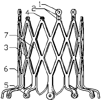
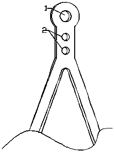
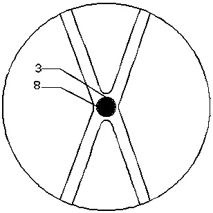
[0091] An interventional prosthetic heart valve, comprising a radially stretchable elastic support, a covering film and at least two leaflets, the covering film is sutured on the inner or outer wall of the support, and the leaflets are arranged on the support In the cavity of the valve leaflet, the lower edge of the valve leaflet is sutured on the membrane, and the adjacent sides of two adjacent valve leaflets are stitched together, and the side edges are sutured on the bracket. The elastic bracket is as follows: Figure 1 to Figure 3 As shown, the stent structure 6 is composed of a closed grid support unit, and the stent 6 includes: a delivery connection part 1, a support unit 7, a leaflet suture hole 2, a leaflet nadir developing hole 3, an upper suture hole 4, and a lower suture hole 5. Developing ball 8; bracket 6 is made of a nickel-titanium tube through laser cutting and heat treatment. After the stent 6 is shaped, it consists of two parts, one part is a tubular structur...
Embodiment 3
[0101] In the interventional heart valve described in Example 2, a barb structure is added to the elastic stent, and the barb extends from the tubular structure part to the skirt-shaped opening structure part and is inclined to the outside of the stent, such as Figure 6~8 shown.
[0102] As an optional manner, the included angle between the barb and the outer surface of the bracket is 10-80 degrees, and further the included angle is 45 degrees.
[0103] As an optional manner, the barbs are arranged at the junction between the bottom row of mesh structure units in the tubular structure portion.
[0104] As an option, the end of the barb is wedge-shaped or needle-shaped.
[0105] As an optional manner, the barbs are straight, "V" or "U". Such as Figure 9 shown.
[0106] As an optional manner, the barb is provided with a developing site. Such as Figure 9 mentioned.
[0107] As an optional manner, the developing site includes a developing hole and a developing medium fil...
PUM
 Abstract
Description
Claims
Application Information
 - R&D
- Intellectual Property
- Life Sciences
- Materials
- Tech Scout
- Unparalleled Data Quality
- Higher Quality Content
- 60% Fewer Hallucinations
Browse by: Latest US Patents, China's latest patents, Technical Efficacy Thesaurus, Application Domain, Technology Topic, Popular Technical Reports.
© 2025 PatSnap. All rights reserved.Legal|Privacy policy|Modern Slavery Act Transparency Statement|Sitemap|About US| Contact US: help@patsnap.com


