Catalytic cracking lifting pipe material feeding mixing section structure for promoting efficient mixing of raw oil and catalyst

A catalytic cracking and riser technology, which is applied in catalytic cracking, cracking, petroleum industry, etc., can solve the problems of increased oil, repeated contact with agents, more severe catalyst back-mixing, and catalyst back-mixing, so as to promote efficient mixing, The effect of shortened time and reduced space

Active Publication Date: 2015-07-15
CHINA UNIV OF PETROLEUM (BEIJING)
View PDF5 Cites 2 Cited by
  • Summary
  • Abstract
  • Description
  • Claims
  • Application Information

AI Technical Summary

Problems solved by technology

[0011] (2) Due to the existence of "secondary flow", in some areas of the feed mixing section of the riser reactor, the catalyst has relatively serious back-mixing Especially in the vicinity of the side wall of the riser, the back-mixing of the catalyst is more severe, which prolongs the residence time of the catalyst and increases the probability of repeated contact between the oil and the agent, resulting in more serious coking
However, these improvements still have deficiencies. The introduction of internal components provides an attachment point for coke accumulation in the feed section.
More importantly, when the nozzle is set up obliquely, the flow state between the raw material jet and the catalyst is "cross-flowing upward", and the speed difference between the oil and the agent is relatively small, so the two generate momentum and mass , heat exchange and thus mixing "intensity" is low
Moreover, the feed form with the nozzles set up obliquely is fundamentally difficult to suppress the generation of secondary flow. Even if internal components and auxiliary gas are installed, it is only a partial improvement, and it is difficult to improve the "first stage" of the feed mixing section. Form a real "full mixed flow", and it is difficult to quickly transition from the "full mixed flow" of the first stage to the "flat flow" of the "second stage" after the mixing is completed

Method used


Image

  • Catalytic cracking lifting pipe material feeding mixing section structure for promoting efficient mixing of raw oil and catalyst
  • Catalytic cracking lifting pipe material feeding mixing section structure for promoting efficient mixing of raw oil and catalyst
  • Catalytic cracking lifting pipe material feeding mixing section structure for promoting efficient mixing of raw oil and catalyst

Examples


Embodiment 1

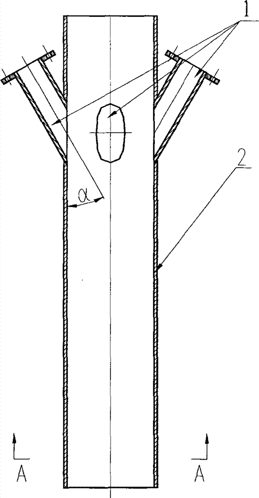
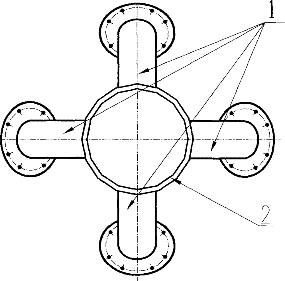
[0032] Such as figure 1 , figure 2 As shown, a catalytic cracking riser feed mixing section structure that promotes the mixing of raw oil and catalyst. In the feed mixing section of the riser, the catalyst flows from the bottom to the top, and the raw oil is sprayed obliquely downward into the feed mixing section of the riser through the nozzle installed in the installation sleeve 1 of the feed oil atomization nozzle. The countercurrent contact of oil and agent forms a "cross-countercurrent" mixed flow, which can strengthen the mixing effect.

[0033] On the pipe wall 2 of the feed mixing section of the riser, the installation sleeve 1 of the raw material oil atomization nozzle is arranged, and the raw material oil atomization nozzle is arranged in the nozzle installation sleeve 1, and the installation sleeve 1 is connected with the riser. The included angle α between the axis of the installation sleeve 1 and the pipe wall 2 of the riser below is 10°-70° obliquely downward,...

Embodiment 2

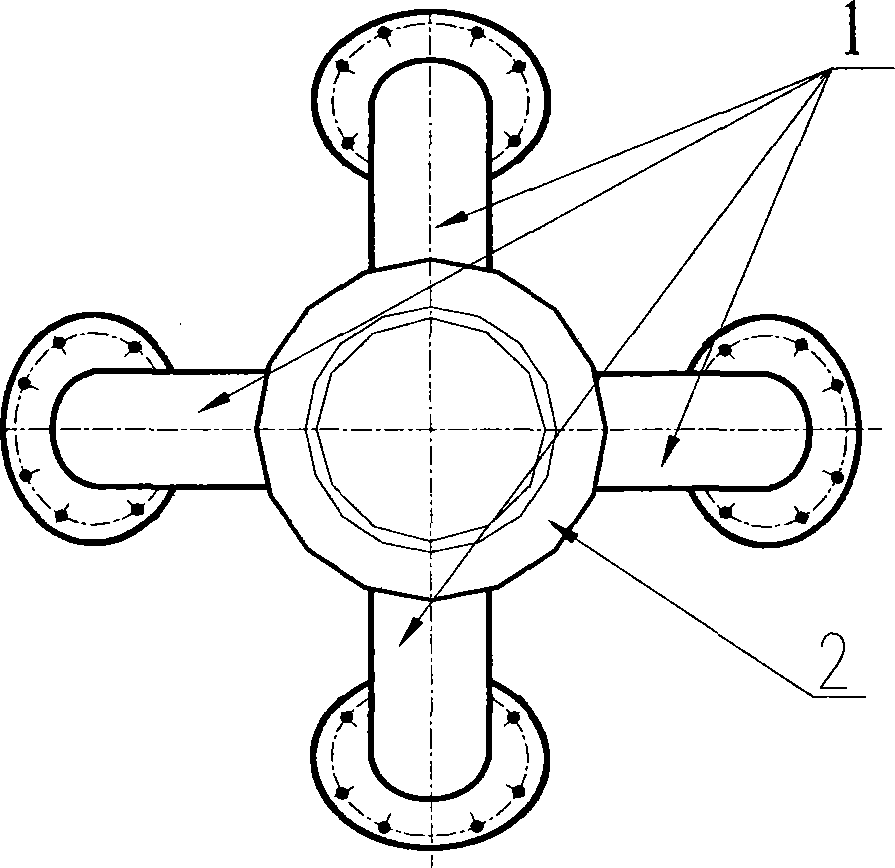
[0036] Such as image 3 , Figure 4 As shown, a catalytic cracking riser feed mixing section structure that promotes the mixing of raw oil and catalyst. In the feed mixing section of the riser, the catalyst flows from the bottom to the top. The raw oil is sprayed obliquely downward into the feed mixing section of the riser through the nozzle installed on the installation sleeve 1 of the raw oil atomization nozzle. The lower riser of the nozzle installation sleeve 1 has a variable diameter, and the cross section of the riser increases from bottom to top, and the expansion angle γ is 2° to 30°, which is 10° in this embodiment. In the feed section of the riser, the oil and the agent are in countercurrent contact, thereby forming a "cross-countercurrent" mixed flow, which can enhance the mixing effect.

[0037] On the pipe wall 2 of the feed mixing section of the riser, an installation sleeve 1 of a raw material oil atomization nozzle is arranged, and a raw material oil atomiza...


PUM


Abstract

The present invention belongs to the technical field of petrochemical industry, and relates to a lifting pipe reactor material feeding mixing section structure for promoting efficient mixing of raw oil and a catalyst in a catalytic cracking process. According to the present invention, a raw oil atomization spraying nozzle adopts an obliquely downward material feeding installation manner along to the axial direction of the lifting pipe so as to achieve oil-catalyst countercurrent contact in the catalytic cracking lifting pipe material feeding mixing section; the raw oil atomization spraying nozzle installation bushing (1) is obliquely and downward arranged on the lifting pipe reactor pipe wall (2) along the axial direction, and the raw oil atomization spraying nozzle is arranged in the raw oil atomization spraying nozzle installation bushing (1); in the used material feeding mixing section structure of the present invention, the raw oil droplets sprayed by the raw oil atomization spraying nozzle and the catalyst particles are subjected to countercurrent contact, such that the state between the raw material jet and the catalyst presents the cross-countercurrent mixing flow so as to improve the oil-catalyst contact and mixing situation in the catalytic cracking lifting pipe material feeding mixing section; and the complete mixing flow is subjected to transition to achieve the plug flow after the raw oil and the catalyst are rapidly mixed so as to reduce the space required by the mixing process, shorten the time required by the mixing process, and improve the reaction efficiency.

Description

technical field [0001] The invention belongs to the technical field of petrochemical industry, and relates to a feed mixing section structure of a riser reactor for promoting efficient mixing of raw oil and catalyst in a catalytic cracking process. Background technique [0002] Catalytic cracking technology occupies a pivotal position in my country's petroleum processing industry, providing more than 70% of gasoline and about 30% of diesel in my country's market. The riser reactor is one of the core devices of catalytic cracking. High-value target products such as gasoline, diesel and liquefied gas are obtained there. [0003] According to the role played in the cracking reaction process, the entire riser reactor can usually be divided into four parts from bottom to top: the pre-lift section, the feed mixing section, the full reaction section and the outlet rapid separation zone. In the pre-lift section , the pre-lift steam (gas) enters from the bottom of the riser, mixes ...

Claims


Application Information

Patent Timeline
Patent Type & Authority Applications(China)
IPC IPC(8): C10G11/00B01J8/08
Inventor 卢春喜范怡平陈昇闫子涵
Owner CHINA UNIV OF PETROLEUM (BEIJING)
Why Eureka
Try Eureka