Method for manufacturing a metallic or ceramic component by selective laser melting additive manufacturing

A laser melting additive, selective technology for the manufacture of metal or ceramic components/three-dimensional products, hot gas path components to achieve novel laser "idle" times, increased production rates, reduced idle times and jump delays

Inactive Publication Date: 2015-07-15
ANSALDO ENERGIA IP UK LTD
View PDF5 Cites 15 Cited by
  • Summary
  • Abstract
  • Description
  • Claims
  • Application Information

AI Technical Summary

Problems solved by technology

This has the disadvantage of having to move heavy

Method used


Image

  • Method for manufacturing a metallic or ceramic component by selective laser melting additive manufacturing
  • Method for manufacturing a metallic or ceramic component by selective laser melting additive manufacturing
  • Method for manufacturing a metallic or ceramic component by selective laser melting additive manufacturing

Examples


Embodiment Construction

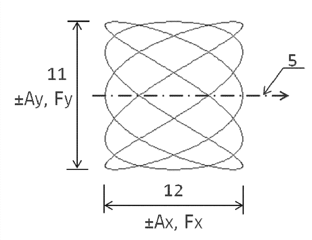
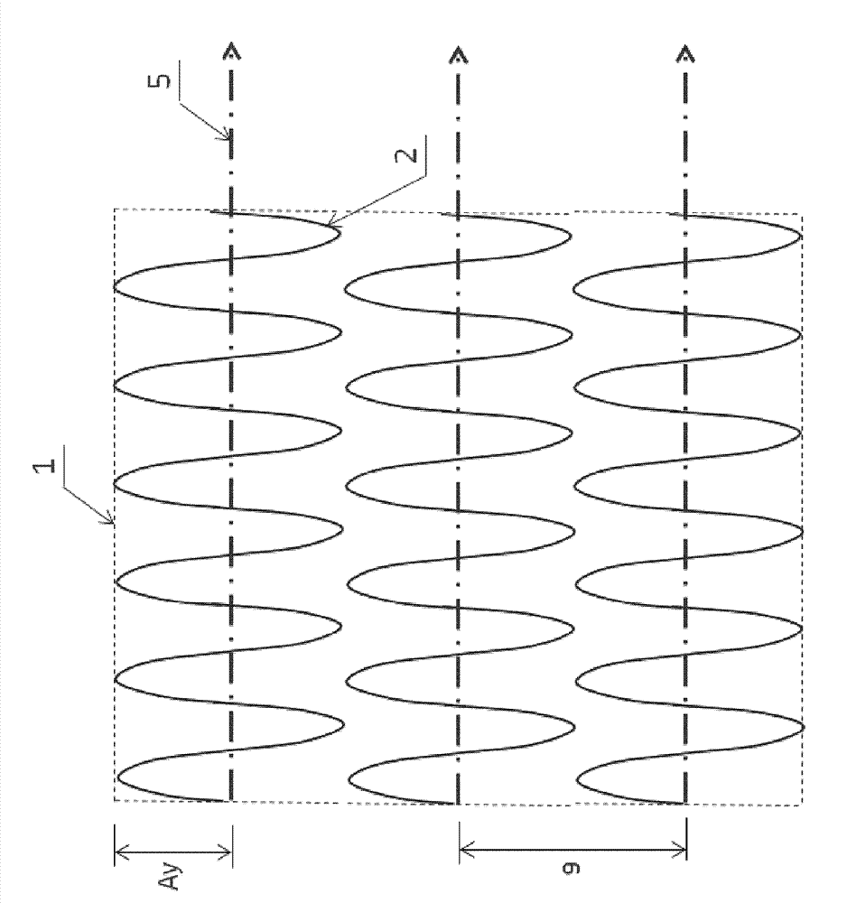
[0051] As mentioned above, the general idea of ​​the method is to use a rocking and scanning strategy by selective laser melting (SLM) to produce functional elements of high design complexity. These additive manufacturing processes will benefit from higher production rates using novel beam scanning techniques.

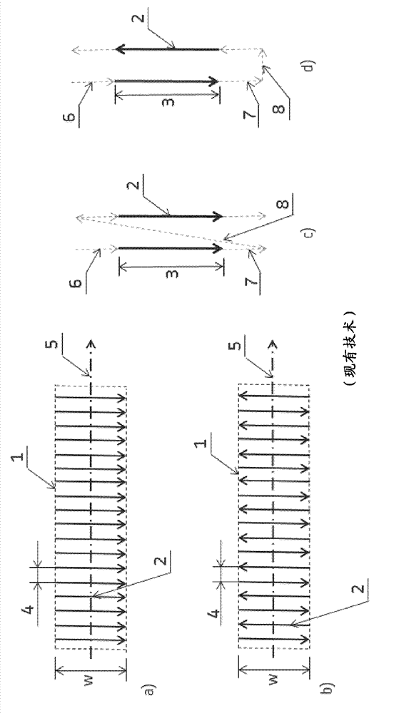
[0052] A good example of such an application is a combustor swirler for a gas turbine, where many sections of large dimensions have to be melted by means of a laser beam. The manufacture of such components usually requires many machine hours. However, a significant portion of the overall fabrication time is "laser idle" time, ie, secondary "non-melt" operations where the laser is switched off and therefore cannot be produced. A typical example is the deposition of a new powder layer, but also the laser reset movement from the end of a melt track to the start of the next melt track with its associated laser on / off delay. A significant portion of this "laser idle" time...


PUM


Abstract

The invention refers to a method for selective laser melting additive manufacturing a three-dimensional metallic or ceramic article / component entirely or partly, comprising the steps of successively building up said article / component layer by layer directly from a powder bed of a metallic or ceramic base material by means of remelting the layers with a high energy laser beam, moving repetitively across the areas, which are to be solidified, wherein the movement of the laser beam is made of a superposition of a continuous linear movement and at least one superimposed oscillation with a determined frequency and amplitude and wherein the oscillation is created by a beam deflection device and the same beam deflection device is also used for linear positioning movement.

Description

technical field [0001] The present invention relates to the art of high temperature resistant components, especially hot gas path components for gas turbines. It relates to a method for manufacturing metallic or ceramic components / three-dimensional articles by selective laser melting (SLM) additive manufacturing technology. Background technique [0002] Additive manufacturing has become an increasingly attractive solution for producing metallic or ceramic functional prototypes and components. For example, SLM and SEBM (Selective Electron Beam Melting) methods use powdered materials as base materials. The powder is melted by laser or electron beam. From the CAD model, there is powder layer deposition and the desired object is built on the platform. This means that components or articles are produced directly from a powder bed by layer-by-layer manufacturing. [0003] Conventional scanning strategies, as they are applied in all SLM machines today, use a centrosymmetric las...

Claims


Application Information

Patent Timeline
IPC IPC(8): C23C24/10B22F3/105B28B1/24
CPCF01D5/284F02C7/24B23P6/007B33Y80/00F01D5/00B22F2003/1057B23K26/00B23K26/345C04B35/64B22F5/009B22F3/1055B33Y10/00B28B1/001F23R3/14F01D25/005B22F5/04C22C32/0026F23R3/002F23R2900/00018F05D2230/31B23K26/32B23K26/342B23K26/082C04B35/653C04B2235/665B23K2101/001B23K2103/02B23K2103/26B23K2103/50B23K2103/52Y02P10/25B22F10/28B22F10/36B22F12/49B22F10/366B22F10/25
Inventor M.帕洛夫M.霍伊贝F.罗伊里格J.舒尔布
Owner ANSALDO ENERGIA IP UK LTD
Why Eureka
Try Eureka