Aluminum electrolysis cell with end face electricity outgoing

An aluminum electrolytic cell and electrolytic cell technology, applied in the field of electrolytic cells, can solve the problems of large horizontal current, large cell spacing, and increased investment costs, and achieve the effects of stable electrolysis, small horizontal current, and reduced investment costs

Inactive Publication Date: 2015-07-15
GUIYANG AL-MG DESIGN & RES INST
View PDF4 Cites 0 Cited by
  • Summary
  • Abstract
  • Description
  • Claims
  • Application Information

AI Technical Summary

Problems solved by technology

[0008] The purpose of the present invention is to provide an aluminum electrolytic cell with end-face electricity discharge to solve the problem that the existing aluminum electrolytic cell is powered from the side and needs to be equipped with a large number of busbars around the cell to pass the side electricity outlet end of the electrolytic cell throug

Method used


Image

  • Aluminum electrolysis cell with end face electricity outgoing
  • Aluminum electrolysis cell with end face electricity outgoing

Examples


Embodiment Construction

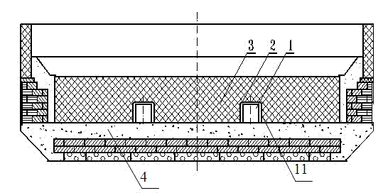
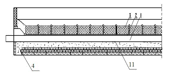
[0018] refer to figure 1 and figure 2 , the aluminum electrolytic cell with end face electricity discharge includes a cathode carbon block 1 and a cathode rod 2, a rod groove 11 is opened on the cathode carbon block 1, and a cathode rod 2 is arranged in the rod groove 11 along its length direction, and the cathode carbon block is fast 1 is set in the tank shell 4 of the electrolytic cell, and the rod groove 11 penetrates the tank shell 4 at the outlet end of the electrolytic cell, so that the electrolytic cell can directly discharge electricity from the outlet end, without the need to discharge electricity from the side and configure a large number of tank side busbars. The slotting direction of the rod groove 11 is parallel to the side of the electrolytic cell where the rod groove 11 is located, and the paste 3 is filled between the cathode rod 2 and the rod groove 11. The paste 3 mainly plays a role of fixing and conducting, and the cathode rod 1 can It is a steel rod or a...


PUM


Abstract

The invention discloses an aluminum electrolysis cell with end face electricity outgoing, is used for solving the problems that because a conventional aluminum electrolysis cell generates electricity from side faces, a large number of cell circumference busbars are required to be constructed, the investment cost is greatly increased, the cell separation distance is relatively large and the land occupation area is increased, and at the same time, the side face electricity outgoing makes the horizontal current quite large and is not conducive to electrolysis cell stability; the aluminum electrolysis cell includes a cathode carbon block and a cathode bar, the cathode carbon block is provided with a bar groove, the bar groove is internally provided with the cathode bar along the length direction, the bar groove passes through a cell shell at an electricity outgoing side of the electrolysis cell. The aluminum electrolysis cell is used for industrial production of metal aluminum.

Description

technical field [0001] The invention relates to an electrolytic cell, in particular to a cathode structure for enabling an aluminum electrolytic cell to discharge electricity at one end of the electrolytic cell adjacent to a downstream cell. Background technique [0002] The current flow direction of the existing aluminum electrolytic cell is as follows: after the current flows through the busbar around the upper tank to the column busbar of the tank, the current flows through the column busbar through the large busbar and the balance busbar, and then flows through the anode through the large busbar, and then flows through the electrolyte and aluminum liquid , and then flow to the cathode, and finally flow from the cathode to the lower platform through the busbar around the tank. [0003] The structure of the cathode carbon block is as follows: each group of cathodes is composed of the following three parts: a cathode carbon block, two or four cathode steel rods, and a paste...

Claims


Application Information

Patent Timeline
IPC IPC(8): C25C3/08
CPCC25C3/08
Inventor 刘正
Owner GUIYANG AL-MG DESIGN & RES INST
Why Eureka
Try Eureka